Hybrid stent

Inactive Publication Date: 2007-01-30
CARDINAL HEALTH SWITZERLAND 515 GMBH
View PDF113 Cites 76 Cited by
  • Summary
  • Abstract
  • Description
  • Claims
  • Application Information

AI Technical Summary

Benefits of technology

[0055]Still another object of the invention is to connect the flexible longitudinal connecting links to the curved sections of the sets of strut members at a point that is close to the line where the diagonal sections join the curved sections, thus further reducing the propensity for end flaring.
[0056]Still another object of the invention is to have flexible longitudinal connecting links that are adapted to readily increase their longitudinal length when the balloon is inflated; thus minimizing the extent of stent foreshortening upon stent deployment.
[0057]Still another object of the present invention to have a stent that has sets of circumferential strut members with tapered curved sections, the center of the curved sections being wider than the ends of the curved sections so as to reduce plastic strain as the stent is expanded as compared to a curved section with uni

Problems solved by technology

Although stents have been used for this purpose for more than ten years, many stent designs still lack the required flexibility and radial rigidity to provide an optimum clinical result.
Another deficiency of open cell stents is that some stent struts members can flare outward (fish scaling) as the stent is advanced through a tight curve.
Although a stent with uniform width of the strut members will function, if the width is increased to add strength or radiopacity, the sets of strut members will experience increased strain upon expansion.
High strain can cause cracking of the metal and potential fatigue failure of the stent under the cyclic stress of a beating heart.
There

Method used


Image

  • Hybrid stent
  • Hybrid stent
  • Hybrid stent

Examples


Embodiment Construction

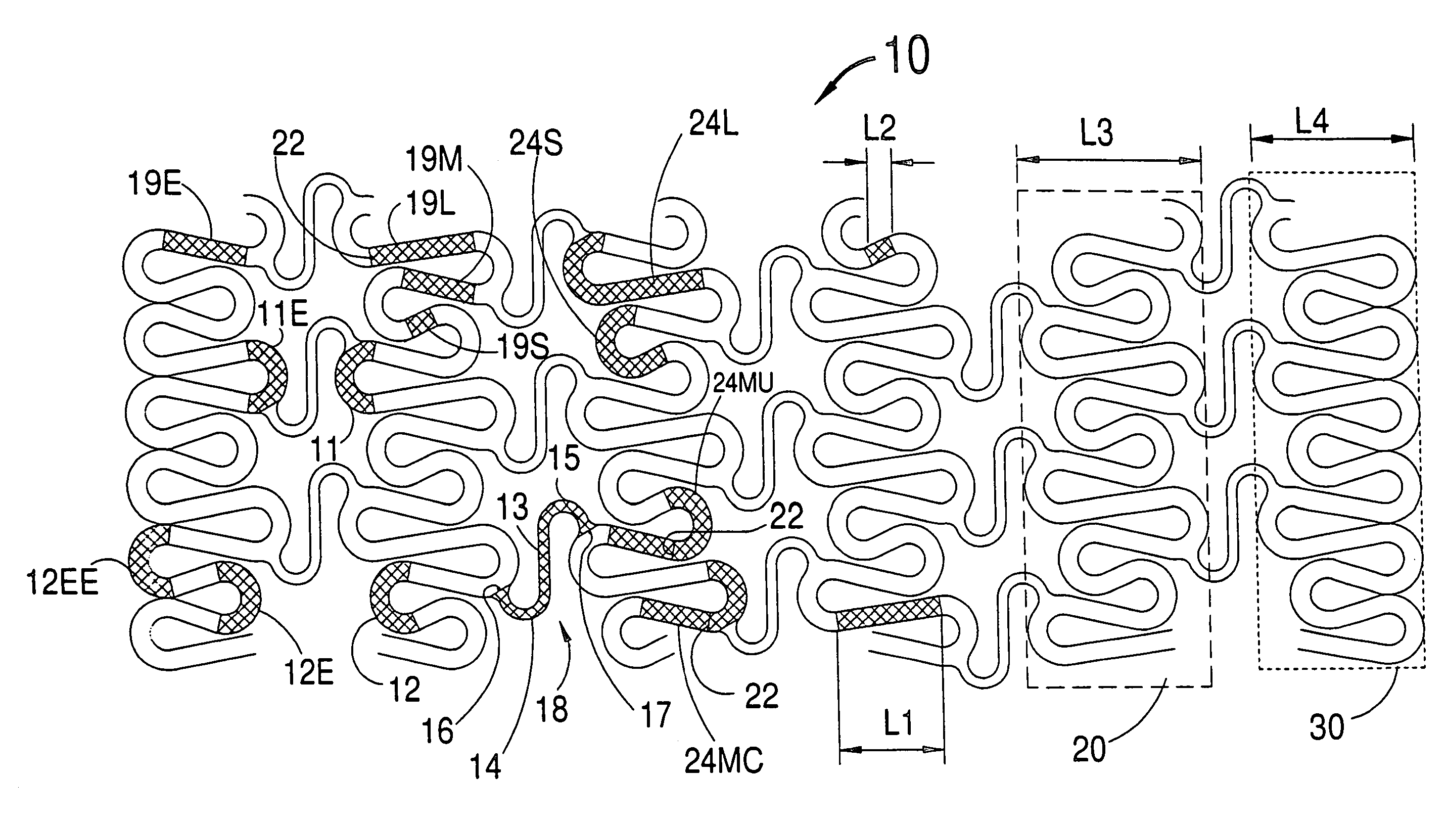
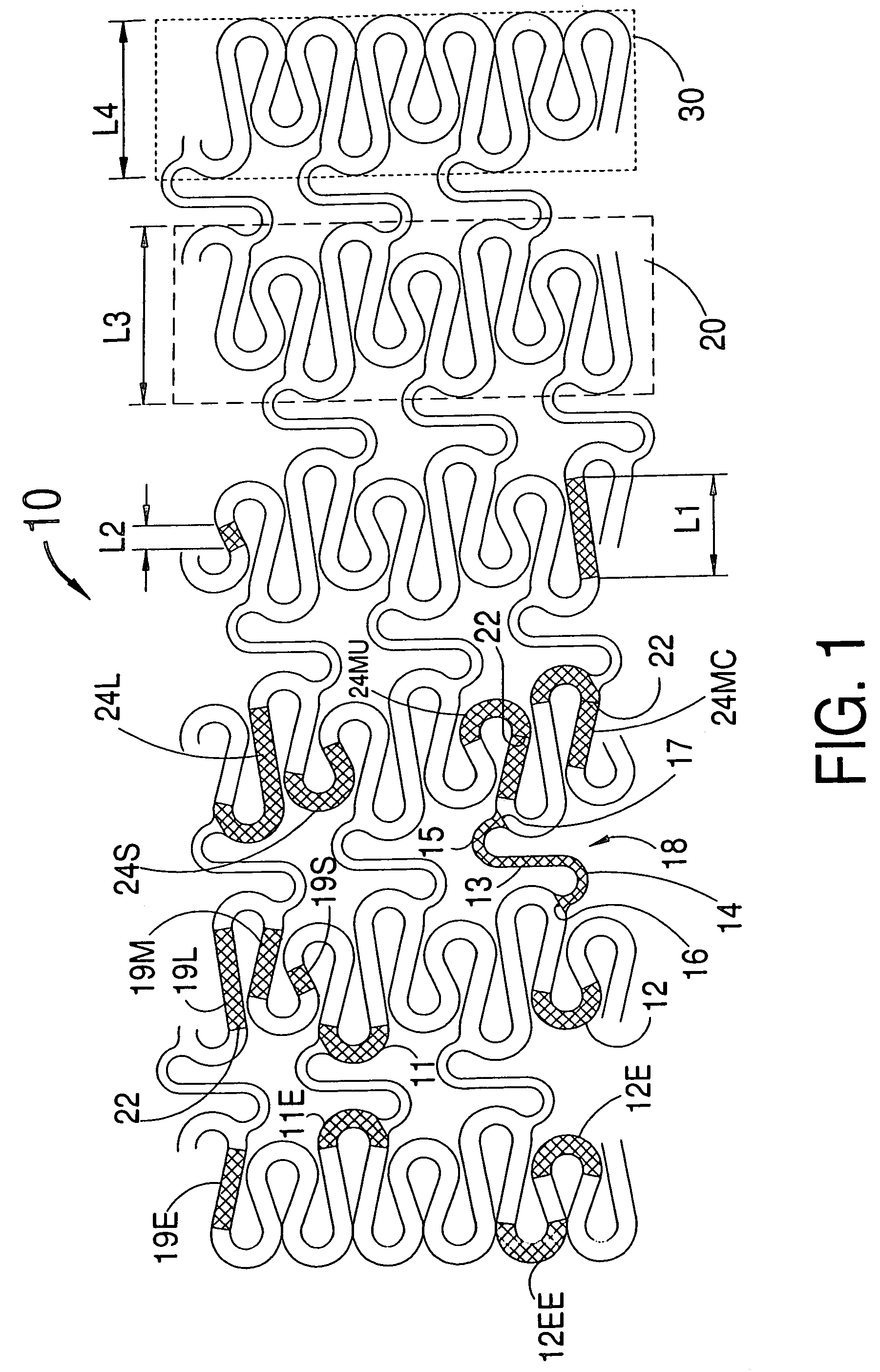
[0077]Although stents are in fact thin-walled, lace-like, cylindrical tubes, they are best illustrated in the form of a flat, two-dimensional layout view as shown in FIGS. 1–7 inclusive.

[0078]FIG. 1 is a flat, layout view of a cylindrical stent 10 wherein each of the stent's top ends would be joined to each of the stent's bottom ends to form the cylindrical stent 10 in its pre-deployed, lace-like, cylindrical form.

[0079]The pre-deployed stent 10 of the present invention is shown in FIG. 1 as having a multiplicity of interior circumferential sets of strut members 20 and two end circumferential sets of strut members 30, each indicated within a dashed rectangle. For the stent 10, the connected curved sections 11 and 11E and the unconnected curved sections 12 and 12E are shown in crosshatch in FIG. 1. Also shown in crosshatch in FIG. 1 is the long diagonal section 19L, medium length diagonal section 19M and short diagonal section 19S. Each of the interior sets of strut members 20 consis...


PUM


Abstract

The present device has increased longitudinal flexibility in a stent by having some curved sections of each circumferential set of strut members being unconnected to the curved sections of the adjacent circumferential set of strut members with the other curved sections being connected by highly flexible, undulating longitudinal connecting links. The present device prevents flaring of the unconnected strut members by having a shorter longitudinal length for the unconnected strut members, and may have generally shorter longitudinal lengths for all the strut members in the circumferential sets of strut members at the stent ends to reduce the tendency for end flaring of the stent. Finally, the stent demonstrates that the flexible longitudinal connecting links of the curved sections of the sets of strut members are connected at a point that is close to the line where the diagonal sections join the curved sections, thus further reducing the propensity for end flaring.

Description

CROSS REFERENCE TO RELATED APPLICATIONS[0001]This application is a continuation of Ser. No. 09 / 718,558, filed Nov. 22, 2000, now U.S. Pat. No. 6,706,061, which is a continuation-in-part of Ser. No. 09 / 607,980, filed Jun. 30, 2000, now U.S. Pat. No. 6,540,775.FIELD OF USE[0002]This invention is in the field of stents for implantation into a vessel of a human body.BACKGROUND OF THE INVENTION[0003]Stents are well known medical devices that have been used for maintaining the patency of a large variety of vessels of the human body. The most frequent use is for implantation into the coronary vasculature. Although stents have been used for this purpose for more than ten years, many stent designs still lack the required flexibility and radial rigidity to provide an optimum clinical result. Another deficiency of open cell stents is that some stent struts members can flare outward (fish scaling) as the stent is advanced through a tight curve.[0004]An open cell stent is defined as a stent that...

Claims


Application Information

Patent Timeline
IPC IPC(8): A61F2/06A61F2/90
CPCA61F2/91A61F2/915A61F2002/91508A61F2002/91516A61F2002/91583A61F2002/91533A61F2002/91541A61F2002/91558A61F2002/91575A61F2002/91525
Inventor FISCHELL, ROBERT E.FISCHELL, DAVID R.FISCHELL, TIM A.
Owner CARDINAL HEALTH SWITZERLAND 515 GMBH
Why Eureka
Try Eureka