Semiconductor device and package, and method of manufacture therefor
a semiconductor device and semiconductor technology, applied in the field of semiconductor devices, can solve the problems of difficulty in downsizing the package, limited number of leads that can be provided for the package, and various problems of conventional semiconductor devices related to soldering, and achieve the effect of easy detection
- Summary
- Abstract
- Description
- Claims
- Application Information
AI Technical Summary
Benefits of technology
Problems solved by technology
Method used
Image
Examples
first embodiment
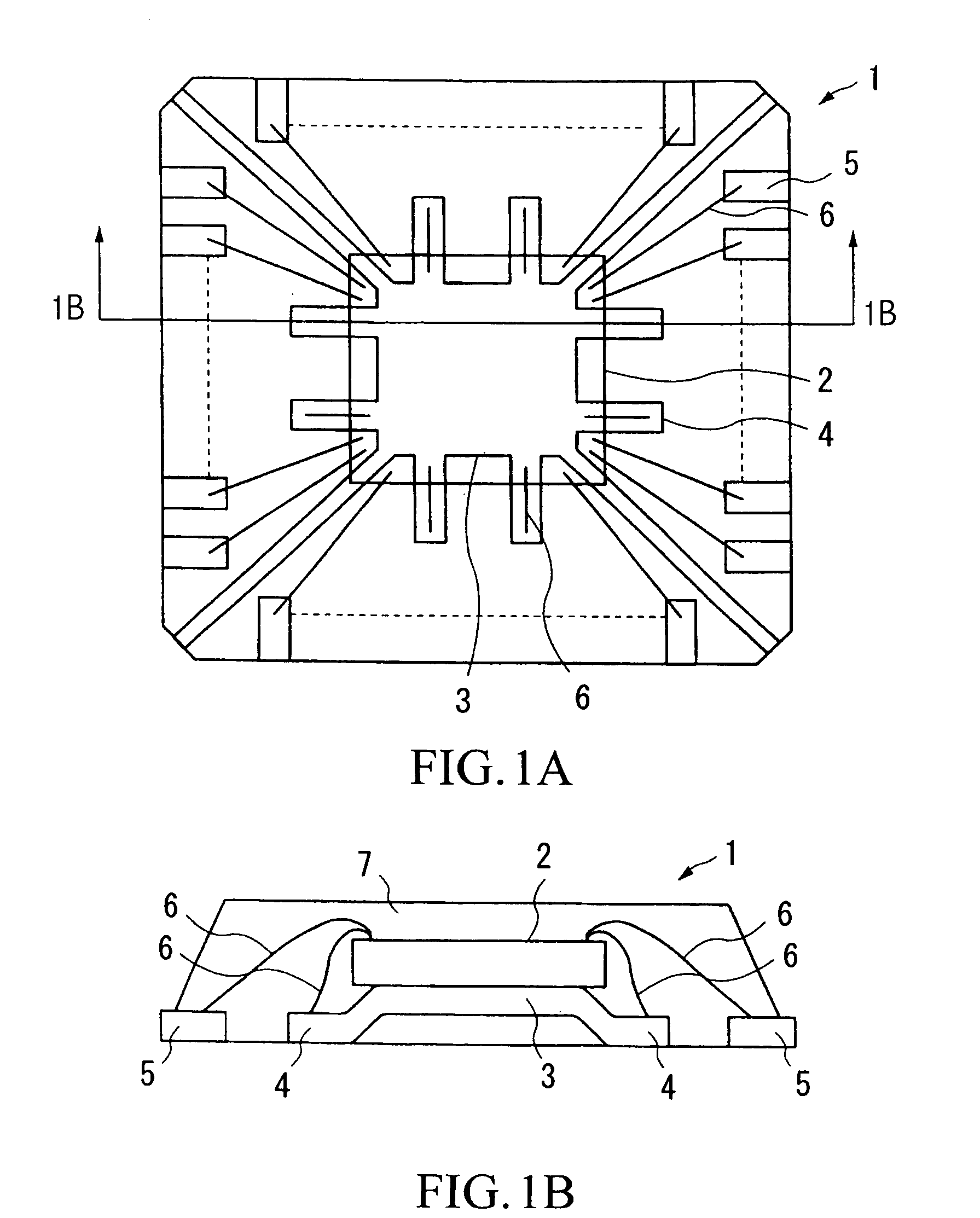
[0060]FIGS. 1A and 1B show the structure and internal configuration of a semiconductor package 1 in accordance with a first embodiment of the invention. Specifically, FIG. 1A is a plan view showing the upper appearance of the semiconductor package 1; and FIG. 1B is a sectional view of the semiconductor package 1 taken along line 1B—1B in FIG. 1A.
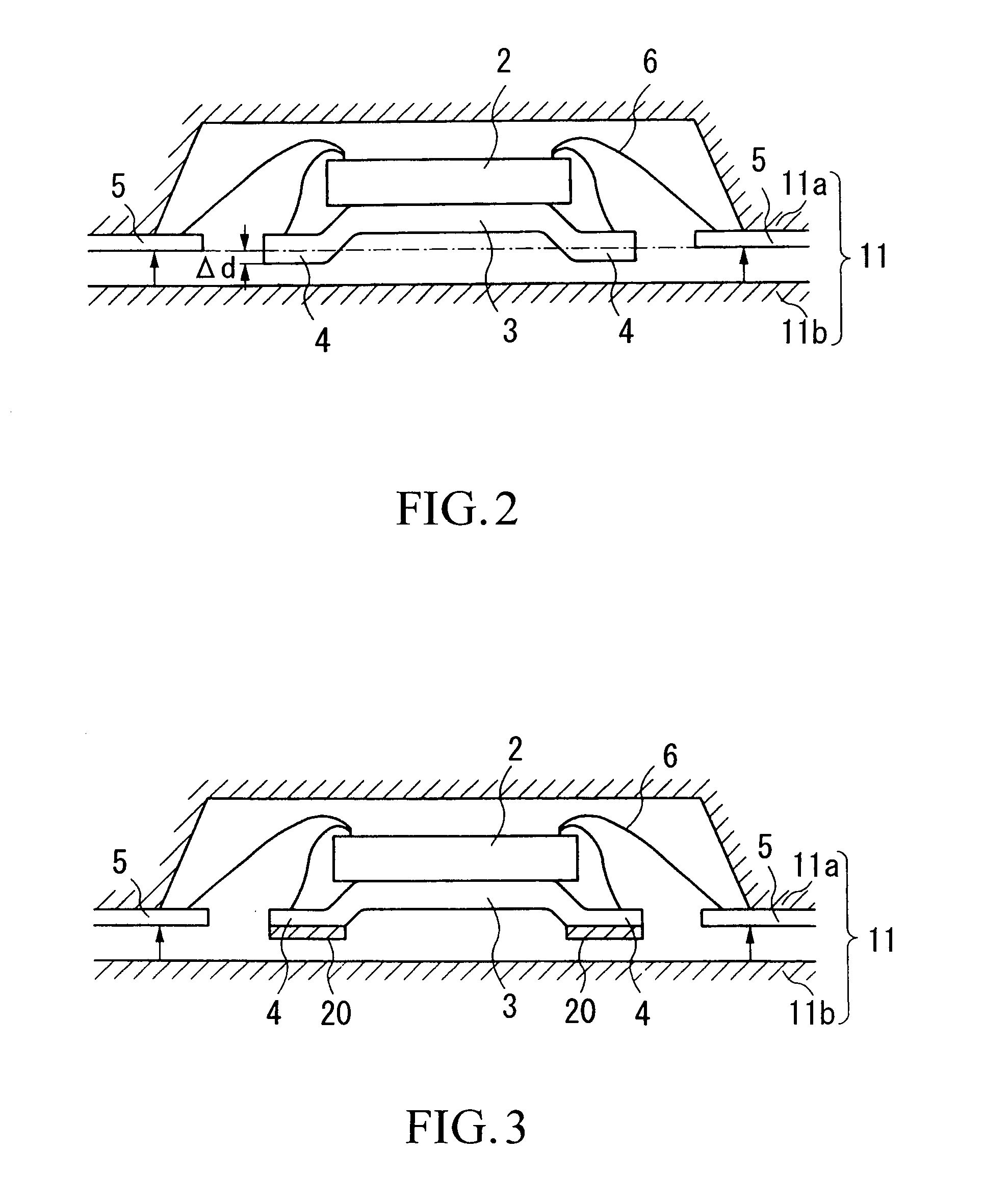
[0061]Reference numeral 2 designates a semiconductor chip, which is supported by a stage 3. Reference numeral 4 designate inner leads that are arranged in the periphery of the stage 3; and reference numeral 5 designate outer leads that are arranged in the outer periphery of the semiconductor package 1 in its bottom. The inner leads 4 and the outer leads 5 are electrically connected together with bonding pads on the semiconductor chip 2 via metal fine lines 6. The aforementioned semiconductor chip 2, stage 3, inner leads 4, and outer leads 5 are all enclosed or sealed within a resin 7, together forming the package 1.
[0062]Compared to the norm...
second embodiment
[0077]FIG. 4 is a sectional view showing selected parts of a semiconductor device in accordance with a second embodiment of the invention. FIG. 5 is a plan view showing an appearance of the semiconductor device that is viewed from its backside (or mounting surface), wherein electrode surfaces are formed to establish connections using external lines.
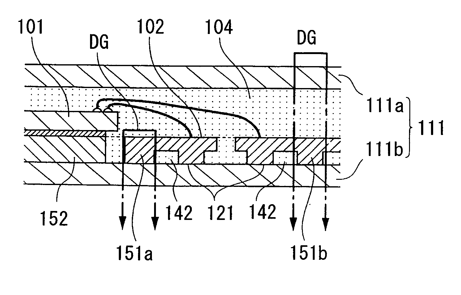
[0078]In the semiconductor device of the second embodiment, pads 101a of a semiconductor chip 101 are electrically connected to terminals 102 via fine lines 103. Herein, the terminals 102 contain inner terminals 102a and outer terminals 102b, which are respectively aligned in an inner line and an outer line in the periphery of a package 104. Both the inner terminal 102a and outer terminal 102b provide electrode surfaces 121, which are exposed externally. The aforementioned elements such as the semiconductor chip 101 and terminals 102 are enclosed or sealed within the package 104 that is composed of a thermosetting resin compound (hereinaf...
third embodiment
[0099]Next, a semiconductor device of a third embodiment of the invention will be described with reference to FIG. 12, wherein the third embodiment is substantially similar to the foregoing second embodiment except for the designated structure for the lead frame 105. Hence, the third embodiment is described with respect to only the structure of the frame 105.
[0100]FIG. 12 is a plan view showing the appearance of one unit of the frame 105, which is viewed from its mounting surface and is used to manufacture the semiconductor device of the third embodiment. Actually, as has been described above numerous units of the frames 105 are horizontally arranged and interconnected together.
[0101]In FIG. 12, the lead frame 105 is made by a metal plate having a substantially externally rectangular shape. A stage 152 for mounting a semiconductor chip 101 is formed substantially at the center of the ‘rectangular’ frame 105. A pair of terminal supports 151a, each of which connects together the presc...
PUM
 Abstract
Description
Claims
Application Information
 - R&D
- Intellectual Property
- Life Sciences
- Materials
- Tech Scout
- Unparalleled Data Quality
- Higher Quality Content
- 60% Fewer Hallucinations
Browse by: Latest US Patents, China's latest patents, Technical Efficacy Thesaurus, Application Domain, Technology Topic, Popular Technical Reports.
© 2025 PatSnap. All rights reserved.Legal|Privacy policy|Modern Slavery Act Transparency Statement|Sitemap|About US| Contact US: help@patsnap.com


