
Internal weight type vertical vibrator

a vertical vibrator, internal weight technology, applied in the direction of mechanical vibration separation, repeater circuit, magnetic body, etc., can solve the problems of limiting the miniaturization and simplification of products, shortening the life of the motor, etc., to improve the vibrating efficiency and increase the degree of freedom in the design of the winding number of the coil

Active Publication Date: 2007-01-30
MPLUS
View PDF13 Cites 21 Cited by
  • Summary
  • Abstract
  • Description
  • Claims
  • Application Information

AI Technical Summary

Benefits of technology

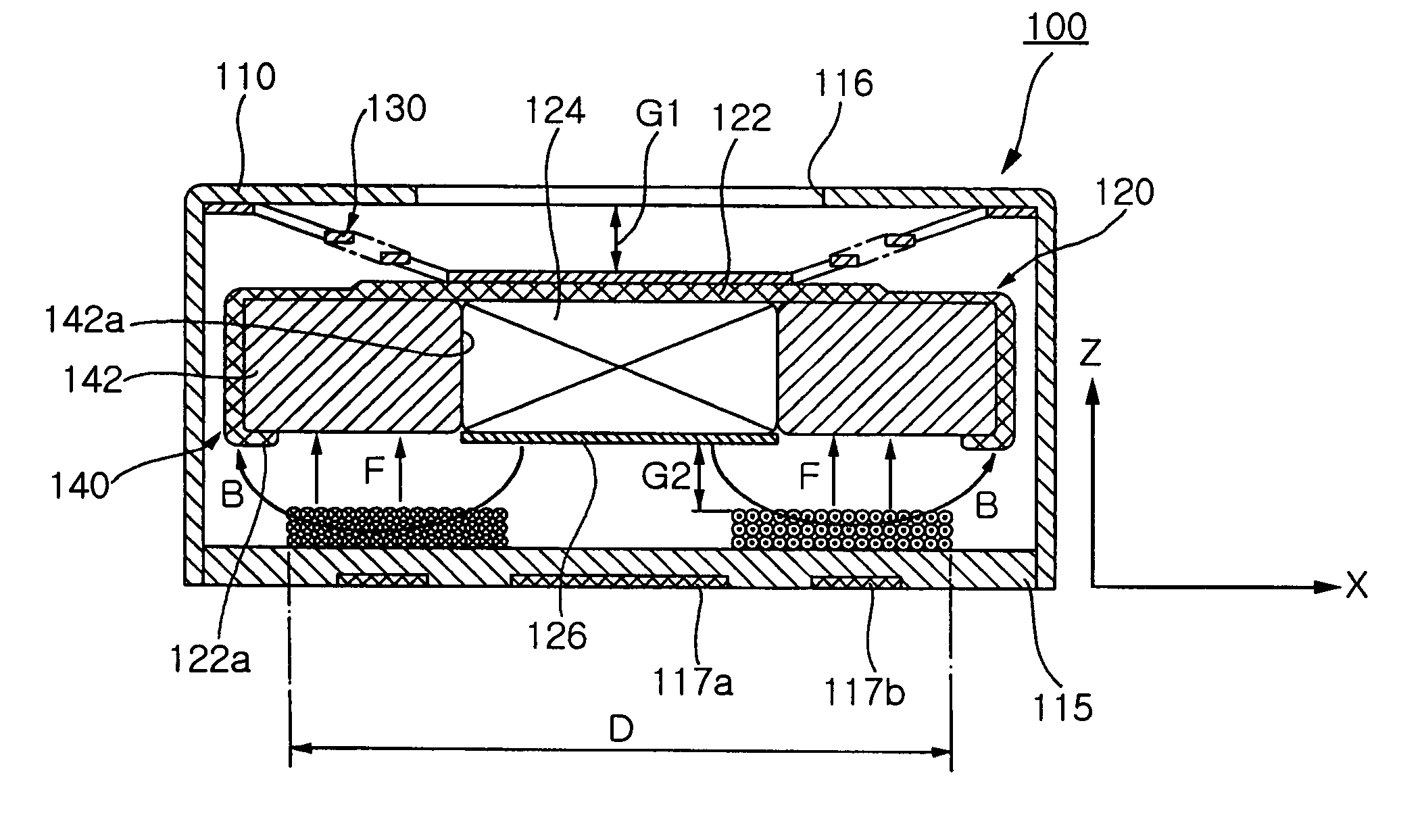
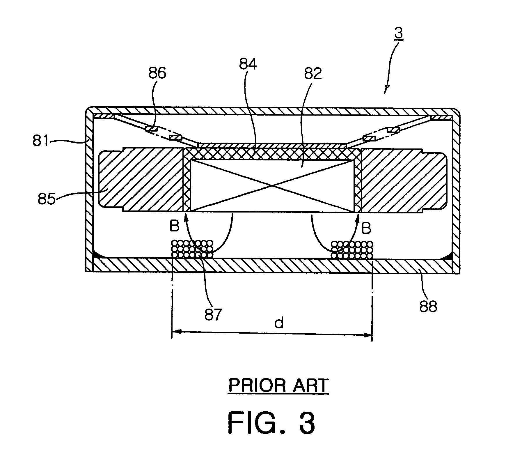
[0027]Therefore, the present invention has been made in view of the above problems, and it is an object of the present invention to provide an internal weight type vertical vibrator, in which the quantity of the magnetic flux of a magnetic field interlinked with a vibration-generating coil is increased to improve vibrating efficiency, the vibration-generating coil is disposed to enlarge an area for generating power inducing exciting force, and the degree of freedom in designing the winding number of the coil is increased.

Problems solved by technology

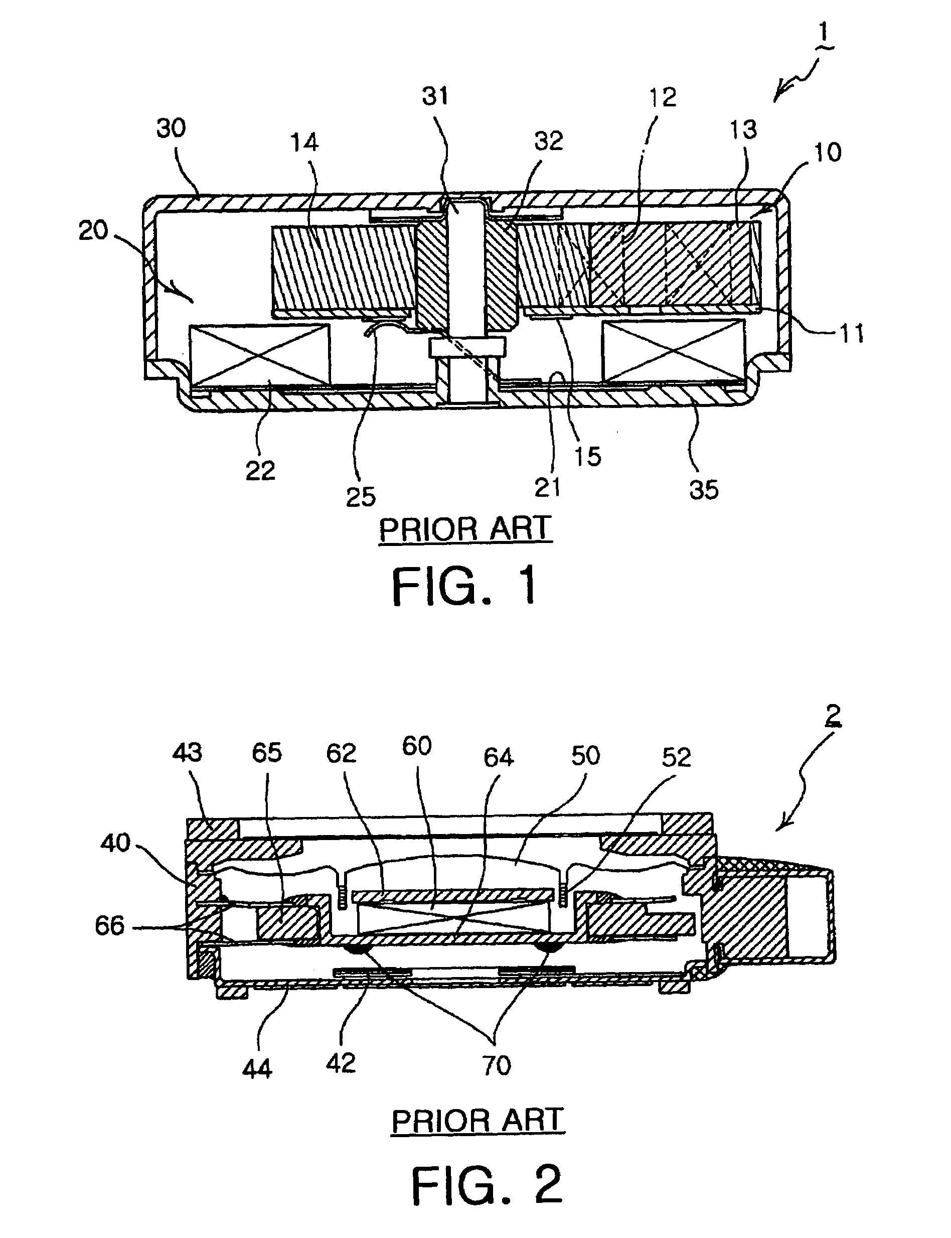
However, when the above-structured vibrating motor 1 is driven, the brushes 25 pass through a gap between segments of the commutator 15, thus causing mechanical friction and electrical sparks between the brushes 25 and the segments of the commutator 15 and abrasion of the brushes 25 and the commutator 15, thereby producing foreign substances, such as black powder and shortening the lifespan of the motor.
The actuator 2 requires a large number of components and has a complicated structure, thus limiting miniaturization and simplification of products and increasing production costs.

Method used


Image

  • Internal weight type vertical vibrator
  • Internal weight type vertical vibrator
  • Internal weight type vertical vibrator

Examples


Embodiment Construction

[0047]Now, preferred embodiments of the present invention will be described in detail with reference to the annexed drawings.

[0048]FIGS. 4a and 4b illustrate an internal weight type vertical vibrator in accordance with one embodiment of the present invention, and FIG. 5 is an exploded perspective view of the internal weight type vertical vibrator in accordance with one embodiment of the present invention. As shown in FIGS. 4a, 4b, and 5, the internal weigh type vertical vibrator 100 increases an area, in which a magnetic field, having a route from a magnet 124 to a yoke 122 through a vibration-generating coil 150, and the vibration-generating coil 150 are interlinked, to increase vibrating efficiency, and enlarges an area for substantially generating force to increase vibrating power in vertical vibration. The vertical vibrator 100 comprises a housing 110, a magnetic circuit unit 120, spring members 130, a vibrating unit 140, and a vibration-generating coil 150.

[0049]That is, the ho...


PUM


Abstract

Disclosed is an internal weight type vertical vibrator including: a housing; a magnetic circuit unit placed in the internal space of the housing, and comprising a magnet perpendicularly placed and a yoke for fixedly receiving the magnet therein for generating a magnetic field; spring members provided with upper ends fixed to the housing and lower ends fixed to the magnetic circuit unit for vertically; a vibrating unit placed in the yoke so that the outer surface of the vibrating unit is surrounded by the yoke, comprising the weight having a hollow cylindrical structure provided with a central hole, into which the magnet is inserted; and a vibration-generating coil placed just below the magnetic circuit unit so that the vibration-generating coil is interlinked with the magnetic field of the magnet for allowing current supplied from the outside to flow in one direction therethrough.

Description

RELATED APPLICATIONS[0001]The present application is based on, and claims priority from, Korean Application Serial Number 2004-50997, filed Jul. 1, 2004, the disclosure of which is hereby incorporated by reference herein in its entirety.BACKGROUND OF THE INVENTION[0002]1. Field of the Invention[0003]The present invention relates to a vertical vibrator, and more particularly to an internal weight type vertical vibrator, in which a yoke surrounds a weight for increasing dimensions of a region, where a coil for current is interlinked with a magnetic field of a magnet, thereby improving vibrating efficiency and vibrating power.[0004]2. Description of the Related Art[0005]Generally, sound and vibration are used to inform users of an incoming call. A small-sized vibrating motor is driven to generate vibration, and driving force of the vibrating motor is transmitted to a housing of a device, thereby vibrating the whole portions of the device.[0006]A vibrating motor, which is one incoming c...

Claims


Application Information

Patent Timeline
Patent Type & Authority Patents(United States)
IPC IPC(8): H02K7/065B06B1/04H02K33/06
CPCB06B1/045H02K33/16H02K33/06B06B1/04
Inventor WON, SUNG HONGCHOI, JOONPARK, IL OUNGKIM, JU HOOH, HWA YOUNG
Owner MPLUS
Learn More