
Vertical vibration forming process and forming device for reinforced concrete pipe

A technology for reinforced concrete pipes and molding equipment, which is applied in reinforcement molding, ceramic molding machines, manufacturing tools, etc., can solve problems such as inability to fully remove air holes in concrete pipes, affecting the quality of reinforced concrete pipes, and unsatisfactory vibrating effects. The effect of good vibrating effect, improving production efficiency and improving quality

Active Publication Date: 2020-08-28
浙江汇博水泥制品有限公司
View PDF9 Cites 8 Cited by
  • Summary
  • Abstract
  • Description
  • Claims
  • Application Information

AI Technical Summary

Problems solved by technology

[0004] Existing reinforced concrete pipes need to be vibrated during the forming process through vertical vibration technology. There are many existing vibrating methods, but the vibrating effect is not ideal enough to fully remove the air holes in the concrete pipes, which seriously affects the strength of steel bars. The quality of concrete pipes, creating a safety hazard

Method used


Image

  • Vertical vibration forming process and forming device for reinforced concrete pipe
  • Vertical vibration forming process and forming device for reinforced concrete pipe
  • Vertical vibration forming process and forming device for reinforced concrete pipe

Examples


Embodiment 1

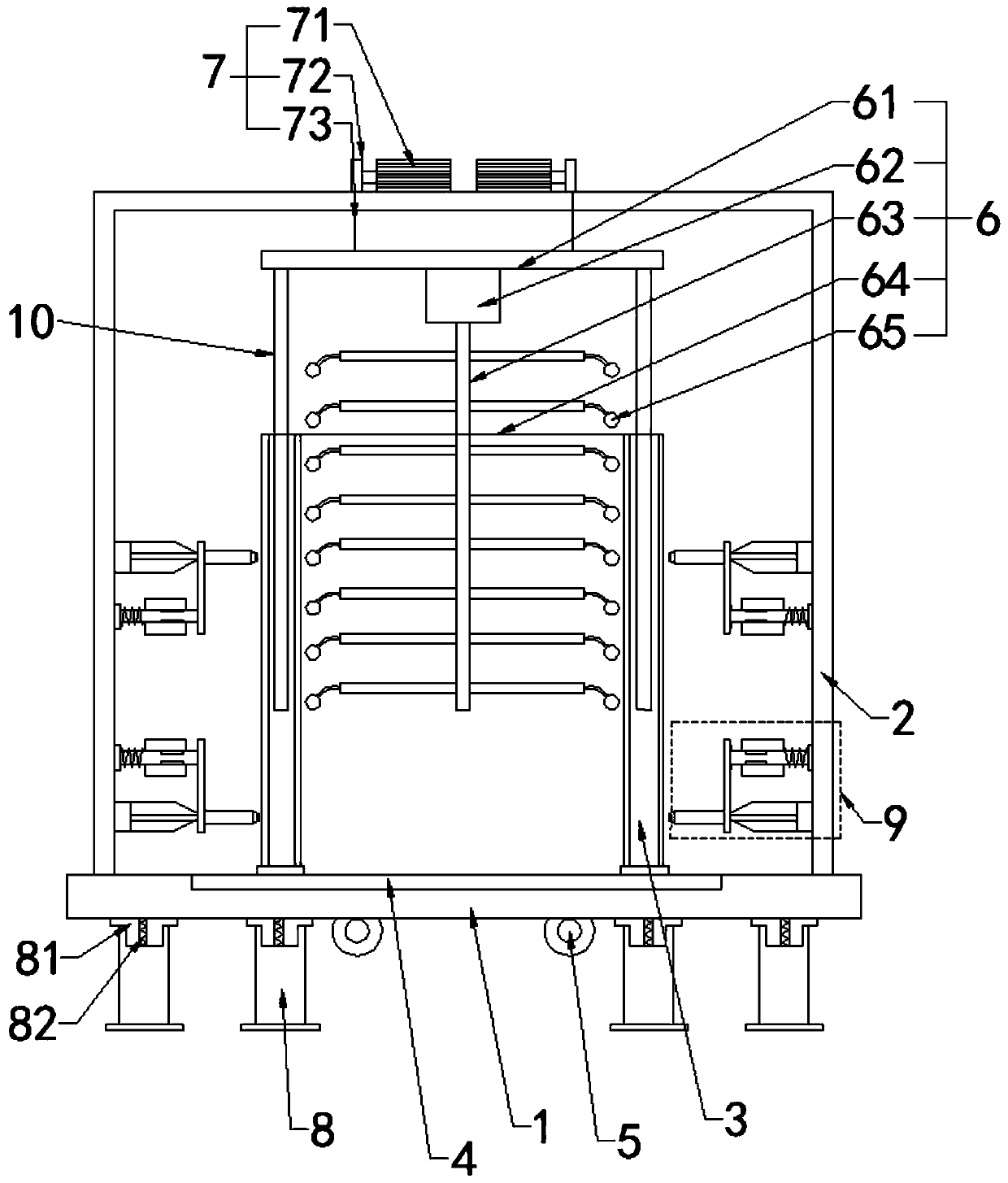
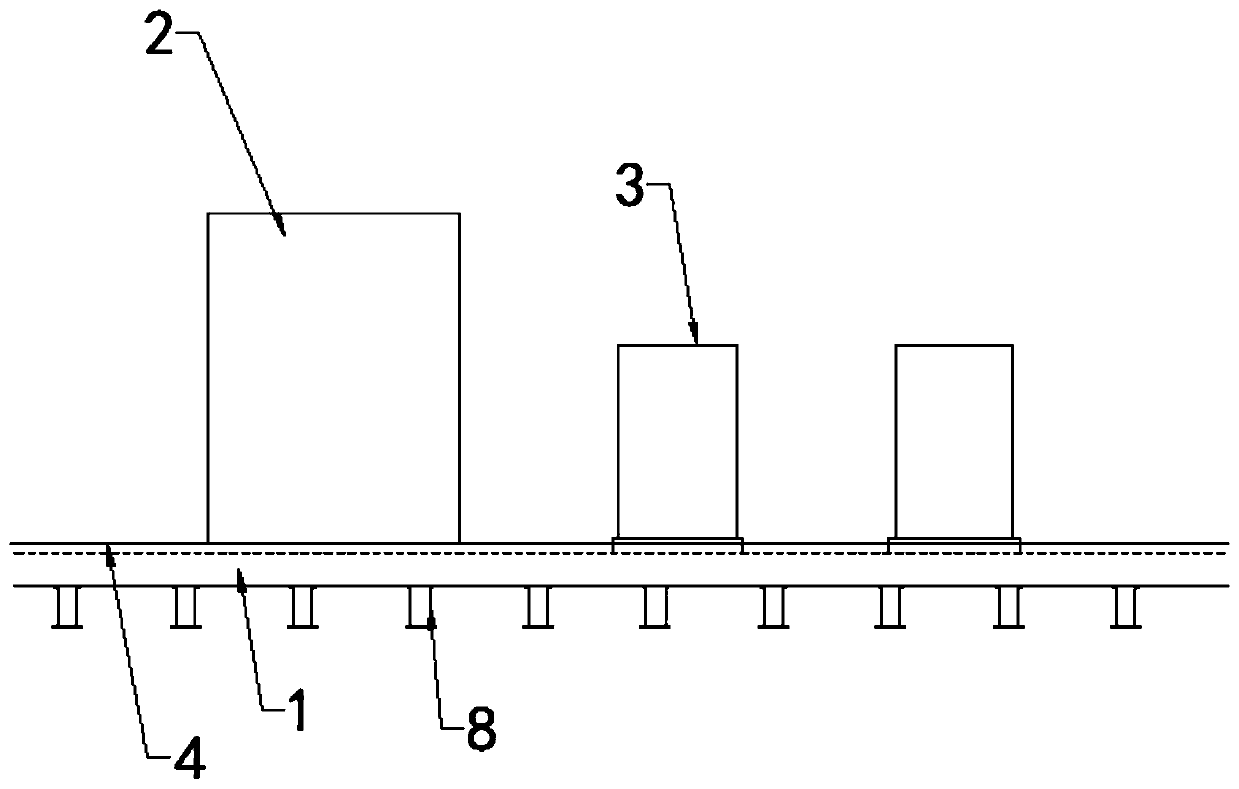
[0029] Such as Figure 1~2 As shown, the present invention discloses a vertical vibrating forming equipment for reinforced concrete pipes. In the embodiment of the present invention, it includes a base 1 and a support frame 2 fixed on the base 1, a pipe mold 3 and a vibrating device. The base 1 is provided with a conveying slide rail 4 for conveying concrete pipes, the conveying slide rail 4 slides on the base 1 for conveying, the pipe mold 3 is installed on the conveying slide rail 4, and the support frame 2 is A rectangular frame with front and rear openings and closed surroundings, the conveying slide rail 4 passes through the support frame 2, and the conveying slide rail 4 can transport the pipe mold 3 from one opening of the support frame 2 to another opening; the vibrating The device includes two sets of mechanical vibrators 5 installed at the lower end of the base 1, the first knocking assembly 6 set in the support frame 2, and the lifting assembly 7 set on the support ...

Embodiment 2

[0038] The invention discloses a vertical vibration molding equipment for reinforced concrete pipes. In an embodiment of the invention, it includes a base 1, a support frame 2 fixed on the base 1, a pipe mold 3 and a vibrating device. The base 1 is provided with a conveying slide rail 4 for conveying concrete pipes, the conveying slide rail 4 slides on the base 1 for conveying, the pipe mold 3 is installed on the conveying slide rail 4, the support frame 2 is opened front and rear and A rectangular frame closed all around, the conveying slide rail 4 passes through the support frame 2, the conveying slide rail 4 can transport the pipe mold 3 from one opening of the support frame 2 to another opening; the vibrating device includes Two groups of mechanical vibrators 5 at the lower end of the base 1, the first knocking assembly 6 arranged in the support frame 2, and the lifting assembly 7 arranged on the support frame 2 and used to control the lifting of the first knocking assembly...


PUM


Abstract

The invention discloses a vertical vibration forming process and a forming device for a reinforced concrete pipe. The vertical vibration forming device comprises a base, and a support frame, a pipe mold and a vibration device mounted on the base, wherein a conveying slide rail is arranged on the base; the pipe mold is mounted on the conveying slide rail; the vibration device includes a mechanicalvibrator, a first knocking module and a lifting module; and the first knocking module includes a hanging disc, a knocking motor, a rotating shaft and a knocking rod. The vertical vibration forming device is excellent in vibration effect and uniform in vibration, improves the quality of the reinforced concrete pipe, is high in vibration efficiency, accelerates vibration forming of the reinforced concrete pipe, and is high in production efficiency.

Description

technical field [0001] The invention relates to the technical field of reinforced concrete pipes, in particular to a vertical vibrating forming process and forming equipment for reinforced concrete pipes. Background technique [0002] The use of concrete pipes is more and more widely used in various fields such as industry and urban construction. The forming process of concrete pipes is characterized by the need to solve technical problems such as forming, exhaust compaction, and mold replacement; the existing concrete pipe forming processes include centrifugal process, suspension Roller technology, vertical vibration technology, mandrel vibration technology and other forms; the pipe has been produced by the traditional high-power rotation or vibration method, the steel skeleton or cage skeleton is installed between the inner and outer molds of the mold, and then Put it on the workbench, use the lifting equipment, pour the concrete into the pipe mold through the concrete unl...

Claims


Application Information

Patent Timeline
Patent Type & Authority Applications(China)
IPC IPC(8): B28B21/16B28B21/12B28B21/56B28B21/90B28B11/24
CPCB28B11/245B28B21/12B28B21/16B28B21/56B28B21/90
Inventor 林玲林峰林耀棋
Owner 浙江汇博水泥制品有限公司
Learn More