Rotor for reluctance type rotating machine

a technology of electric rotating machines and rotors, which is applied in the direction of magnetic circuit rotating parts, synchronous motors, magnetic circuit shapes/forms/construction, etc., can solve the problems of vibration noise, vibration ripple, oscillation, etc., and achieve the effect of reducing the harmonic value of the counter electromotive for

Active Publication Date: 2007-01-30
KK TOSHIBA +1
View PDF10 Cites 53 Cited by
  • Summary
  • Abstract
  • Description
  • Claims
  • Application Information

AI Technical Summary

Benefits of technology

[0008]Therefore, an object of the present invention is to provide a rotor for a reluctance type rotating machine which can achieve the similar effects to those achieved by skew and reduce torque ripple, oscillation, vibration and noise.
[0010]In the above-described construction, the core materials constituting at least one block are formed so that the magnetic concave and convex portions are shifted by a predetermined angle from the core materials constituting the other or another block relative to a center line passing the key. Accordingly, for example, a center line passing the center of the magnetic concave portion of at least one block has a locus shifted from one of another or the other block. Consequently, since the similar effects to those achieved by skew can be achieved, the torque ripple, oscillation, vibration and noise can be reduced.
[0012]A magnetic torque by the permanent magnets can also be achieved in addition to reluctance torque. Furthermore, harmonic values of counter electromotive force can be reduced by the similar effects to those achieved by skew.

Problems solved by technology

It is well known that squirrel-cage induction motors result in crawling due to torque developed by high harmonics.
There is a possibility that permanent-magnet reluctance type rotating machines as the reluctance type rotating machine may cause the similar crawling to that caused by the squirrel-cage induction motors.
As a result, the crawling results in torque ripple, oscillation, vibration and noise.

Method used


Image

  • Rotor for reluctance type rotating machine
  • Rotor for reluctance type rotating machine
  • Rotor for reluctance type rotating machine

Examples


first embodiment

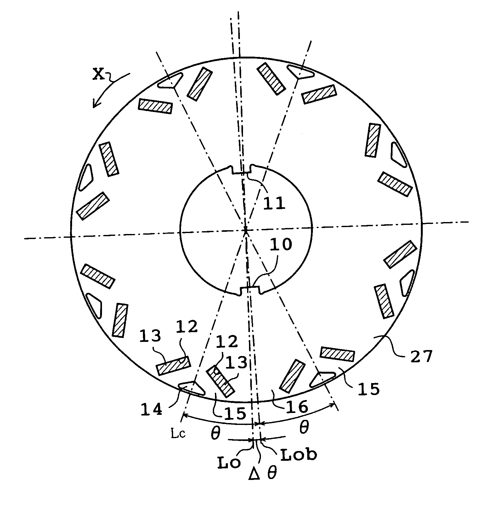
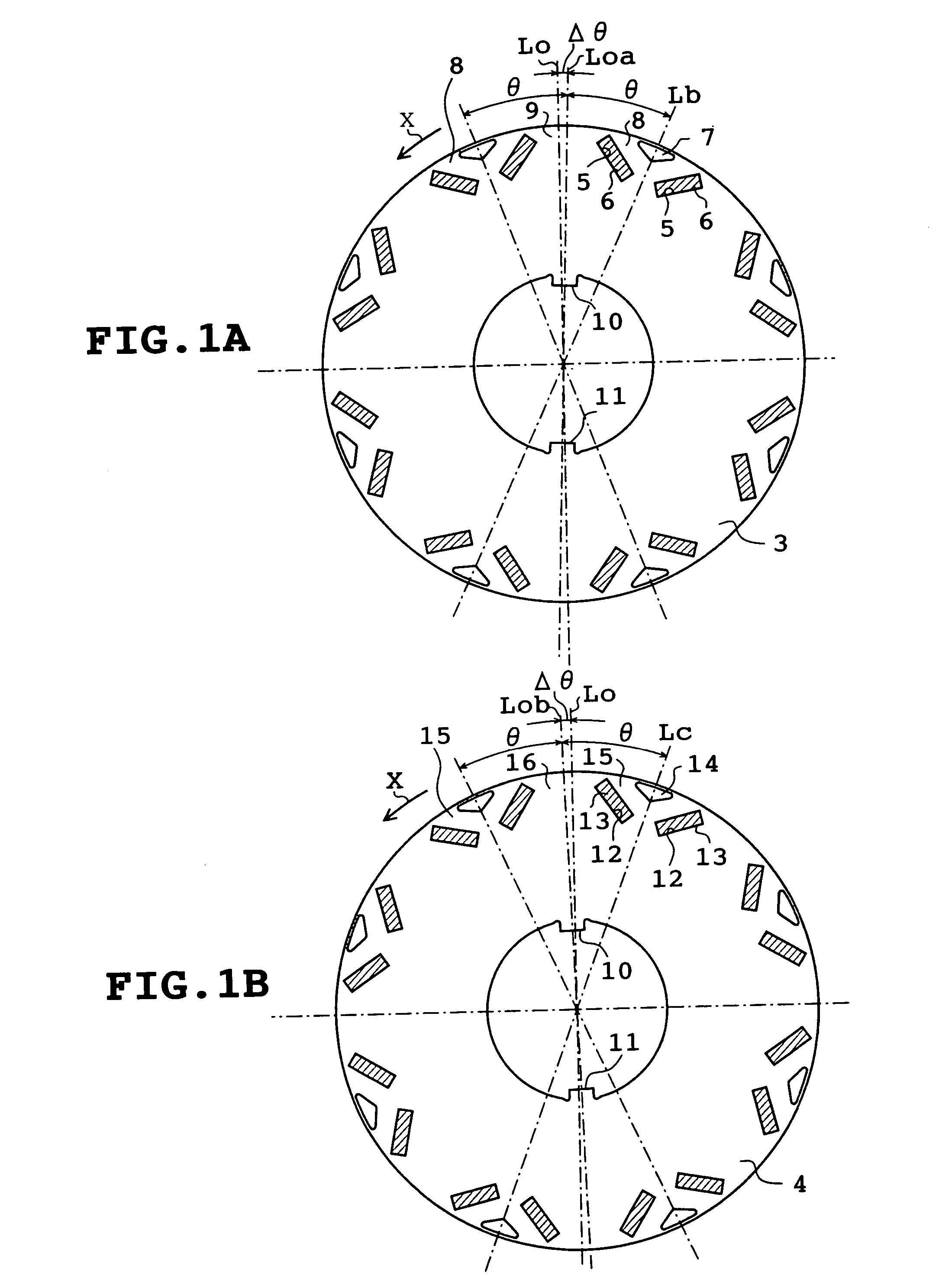
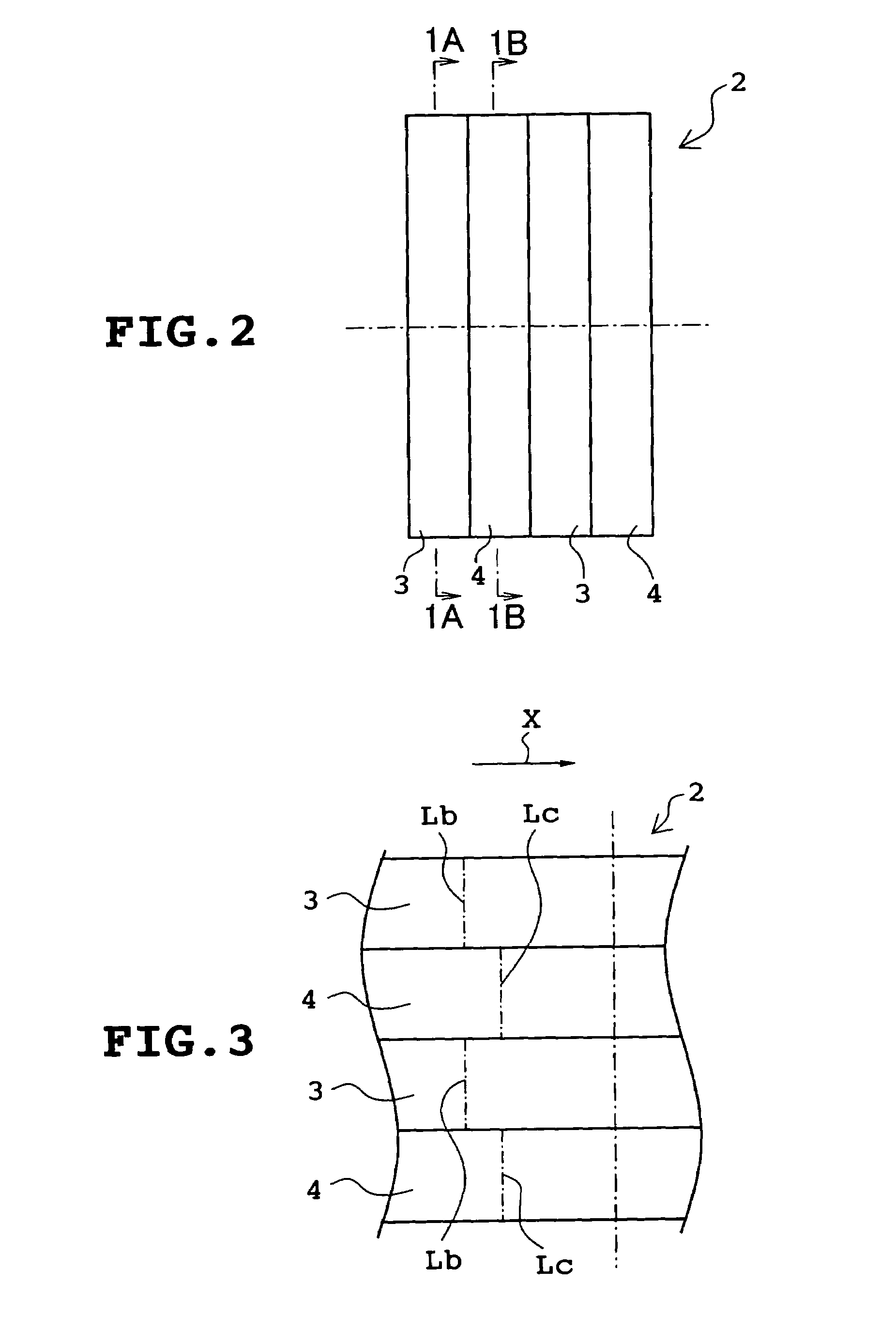
[0031]Several embodiments of the present invention will be described. FIGS. 1A to 5 illustrate a first embodiment in which the invention is applied to a reluctance type rotating machine with permanent magnets. The reluctance type rotating machine possesses eight poles. A rotor 1 of the reluctance type rotating machine includes a rotor core 2 made by stacking a number of annular silicon steel sheets serving as a core material. The rotor core 2 is divided into four blocks 3 and 4 having the same thickness as shown in FIG. 2. The blocks 3 and 4 are stacked alternately.

[0032]Each block 3 or the silicon steel sheets composing each block 3 will be described with reference to FIG. 1A. Each block 3 has a number of pairs of generally rectangular magnet insertion holes 5 formed in an outer circumferential portion thereof. The paired magnet insertion holes 5 are opposed to each other so that a distance therebetween is gradually rendered longer as the magnet insertion holes 5 approach an outer ...

second embodiment

[0046]The annular silicon steel sheets constituting the rotor core 26 are formed by punching a rolled elongated silicon steel sheet. It is well known that the rolling results in shift in the thickness in the rolling direction and in the direction perpendicular to the rolling direction. In the second embodiment, however, the blocks 27 obtained by turning the blocks 4 circumferentially by 180 degrees. Consequently, since the deviation in the thickness is absorbed, the thickness of the rotor core 26 can be rendered uniform.

[0047]The thicknesses of the four blocks 3 and 27 are equal to one another in the second embodiment. However, the total thickness of the blocks having the respective center lines Lb may be equal to the total thickness of the blocks having the respective center lines Lc.

[0048]FIGS. 9 to 11 illustrate a third embodiment of the invention. Describing the difference of the third embodiment from the first embodiment, the rotor core 28 employed instead of the rotor core 2 i...

fifth embodiment

[0056]The portions 43a and 43b and the portions 44a and 44b constituting the respective blocks 43 and 44 are set at one halves of the thicknesses of the blocks 43 and 44 respectively in the However, these portions may be set substantially at one halves respectively.

[0057]The permanent magnets are provided on the rotor core in each of the foregoing embodiments. However, the permanent magnets may or may not be provided on the rotor core. Further, the generally triangular cavities are formed in the rotor core so as to compose the concave and convex portions in each of the foregoing embodiments. However, the cavities may be circular, elliptic, rectangular or rhombic. Additionally, the rotor core may have mechanical concave and convex portions formed therein so that the magnetic concave and convex portions are formed.

[0058]The number of poles of the rotor should not be limited to eight. The same effect can be achieved even when the number of poles is any other number. Furthermore, the n...


PUM

PropertyMeasurementUnit
angleaaaaaaaaaa
magneticaaaaaaaaaa
distanceaaaaaaaaaa

Abstract

A rotor for a reluctance type rotating machine includes a rotor core formed by stacking a number of annular core materials each of which includes magnetic concave and convex portions. The rotor core has two keys which are formed at two positions on an inner circumference of the rotor core. The positions are spaced 180 degrees apart from each other with respect to the rotor core. The rotor core is divided into a plurality of blocks and the core materials constituting at least one block have the magnetic concave and convex portions shifted by a predetermined angle relative to the core materials constituting the other or another block on the basis of a center line passing through the keys. A whole or part of the core materials of at least one block are located circumferentially 180 degrees apart form the core materials constituting the other or another block.

Description

BACKGROUND OF THE INVENTION[0001]1. Field of the Invention[0002]This invention relates to a rotor for a reluctance type electric rotating machine which can achieve the similar effects to those achieved by skew.[0003]2. Description of the Related Art[0004]A reluctance type rotating machine or, for example, a reluctance type rotating machine provided with permanent magnets includes a rotor formed with a magnetic convex portion where a flux is easy to pass (d axis) and a magnetic concave portion where a flux is difficult to pass (q axis) and a permanent magnet which is disposed in a stator provided with a stator winding. The magnetic convex portion (d axis) has a high magnetic flux density in an air gap, whereas the magnetic concave portion (q axis) has a low magnetic flux density in an air gap. These variations in the magnetic flux density produce reluctance torque. Furthermore, torque is also developed by a magnetic attractive force and a magnetic repulsive force between poles of the...

Claims


Application Information

Patent Timeline
Patent Type & Authority Patents(United States)
IPC IPC(8): H02K21/12H02K1/27H02K19/10H02K21/14
CPCH02K1/2766Y10T29/49012H02K2201/06
Inventor ARAKI, TAKASHIMATSUBARA, MASAKATSUMOCHIZUKI, MOTOYASUKAZAO, YUKIHIKOARATA, MASANORIHIRANO, YASUOAIKURA, NOBUTAKEKONDOU, AKITOYAMASHIKI, MASAHIKOOHASHI, MASANORIHANAI, TAKASHI
Owner KK TOSHIBA
Why Eureka
Try Eureka