
Low voltage bandgap reference (BGR) circuit

a low-voltage bandgap reference circuit and reference circuit technology, applied in the direction of electric variable regulation, process and machine control, instruments, etc., can solve the problems of inability to approach a stable operation, inability to use a new bandgap reference circuit technique, and inability to stabilize the operation

Active Publication Date: 2007-01-30
ETRON TECH INC
View PDF14 Cites 29 Cited by
  • Summary
  • Abstract
  • Description
  • Claims
  • Application Information

AI Technical Summary

Benefits of technology

The present invention provides circuits and methods for a temperature independent voltage bandgap reference circuit that can work down to sub-1-Volt. The circuit utilizes standard CMOS processes and is stable at supply voltages below 1.5 V. The circuit allows adjustment of the positive and negative temperature coefficients and can be used for a fractional bandgap reference voltage. The fractional bandgap reference voltage is temperature independent. The technical effects of the invention include improved accuracy and stability of reference voltages and improved performance of electronic devices that use reference voltages.

Problems solved by technology

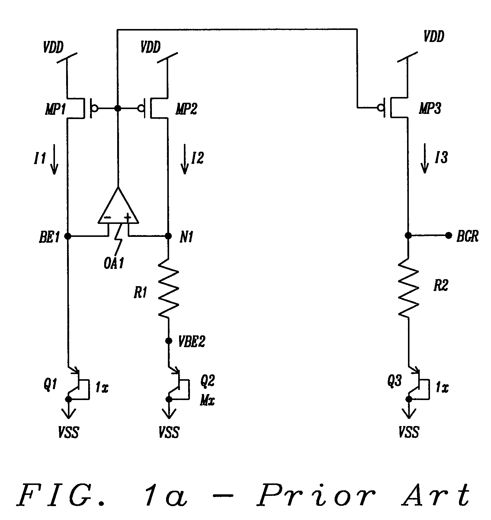
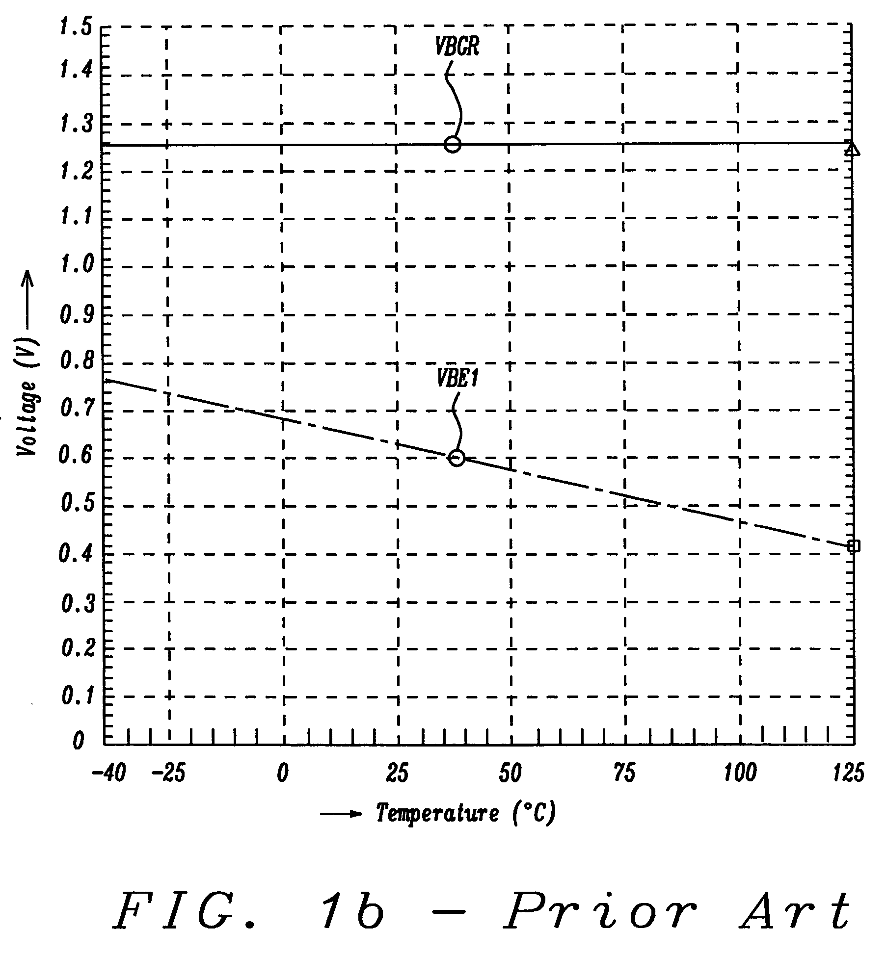
It is difficult to approach a stable operation in conventional bandgap reference (BGR) circuits when the supply voltage is under 1.5 V. As a result, the demand for a new bandgap reference circuit technique which is stable and operated at low supply voltages is inevitable.
A problem of many of the prior art circuits is that they tend not to be stable until the supply voltage is larger than 1.5 V or require additional components, such as capacitors which take considerable area, for stable operation at low supply voltages.

Method used


Image

  • Low voltage bandgap reference (BGR) circuit
  • Low voltage bandgap reference (BGR) circuit
  • Low voltage bandgap reference (BGR) circuit

Examples


Embodiment Construction

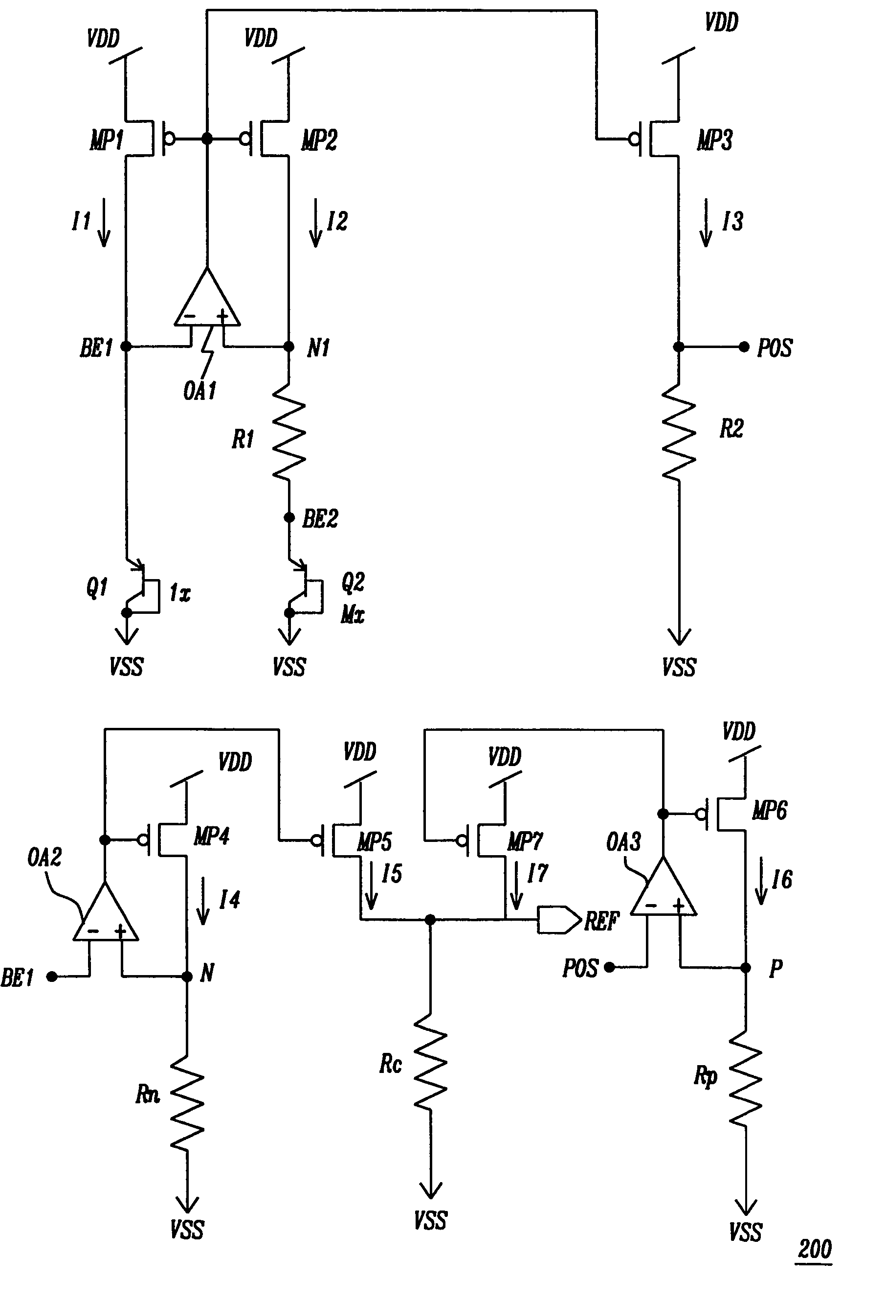
[0052]A new low voltage bandgap reference circuit (BGR) is proposed which will be described in detail below. The circuit uses current summation techniques to implement the temperature compensation and is capable of working down to sub-1-V using standard CMOS processes.

BGR Circuit 1

[0053]Circuit 200 of FIG. 2a illustrates a first preferred embodiment of the present invention. FIG. 2a comprises a CMOS op-amp OA1, a current mirror with PMOS transistors MP1, MP2, MP3, diode-wired transistors Q1, Q2, and resistors R1, R2, all implemented in the standard CMOS process. VDD and VSS are the positive and negative power supply rails, respectively. Nodes BE1 and N1 are coupled to the minus and plus inputs of OA1, respectively. Nodes BE1 (alternatively node BE2) and POS are outputs which connect to inputs of op-amps OA2, OA3, respectively, described next. Resistor R1 is coupled between node N1 and Q2, resistor R2 is coupled between node POS and VSS. The area ratio of Q1 and Q2 is Q1:Q2=1:M. Curr...


PUM


Abstract

A low voltage bandgap reference circuit based on a current summation technique where reference voltages with positive and negative temperature coefficients are generated by a first circuit. These reference voltages are coupled to amplifying circuits which generate reference voltages with equal and opposite temperature coefficients based on the ratio of resistors in these amplifying circuits, thereby producing a temperature independent reference voltage. The current from each of these amplifying circuits is then summed in a summing resistor, where the size of the resistor determines the magnitude of the temperature independent reference voltage.

Description

BACKGROUND OF THE INVENTION[0001]1. Field of the Invention[0002]The invention relates to temperature-stabilized reference voltage circuits, and more particularly to a sub-1-V bandgap reference circuit using a low supply voltage.[0003]2. Description of the Related Art[0004]Reference circuits are necessary in many applications ranging from memory, analog, mixed-mode to digital circuits. The demand for a low voltage reference is especially apparent in mobile battery-operated products. Low voltage operation is also a trend of process technology advancement. It is difficult to approach a stable operation in conventional bandgap reference (BGR) circuits when the supply voltage is under 1.5 V. As a result, the demand for a new bandgap reference circuit technique which is stable and operated at low supply voltages is inevitable.For a discussion of bandgap reference circuits with below 1.5 V power supply voltages refer to:[0005]H. Banba, H. Shiga, A. Umezawa, T. Miyaba, T. Tanzawa, S. Atsumi...

Claims


Application Information

Patent Timeline
Patent Type & Authority Patents(United States)
IPC IPC(8): G05F1/10
CPCG05F3/30
Inventor HSU, JENSHOU
Owner ETRON TECH INC
Learn More