Crystal oscillator with wide tuning range

a crystal oscillator and tuning range technology, applied in the field of crystal oscillators, can solve the problems of not being able to bring the frequency back to the desired value, being difficult to achieve long-term aging, and limited tuning range of a typical crystal oscillator

Active Publication Date: 2007-01-30
NORTHROP GRUMMAN SYST CORP
View PDF2 Cites 12 Cited by
  • Summary
  • Abstract
  • Description
  • Claims
  • Application Information

AI Technical Summary

Benefits of technology

[0009]A crystal oscillator is provided having an oscillatory signal loop feedback path, and which includes a crystal filter incorporating a plurality of crystals such that the center of the crystal filter passband is nominally at the intended oscillator RF operating frequency. A voltage controlled phase shifter having an input, an output and a control input is used to intentionally introduce phase shift in the signal passing through it in the feedback loop in response to a voltage applied to the control input. The phase shifter RF output is fed to the input of an RF amplifier for providing requisite signal

Problems solved by technology

The tuning range of a typical crystal oscillator is however limited to a small tuning range such that it may not be possible to bring the frequency back to the desired value if the output frequency drifts too far.
Long-term aging is a particular problem

Method used


Image

  • Crystal oscillator with wide tuning range
  • Crystal oscillator with wide tuning range
  • Crystal oscillator with wide tuning range

Examples


Embodiment Construction

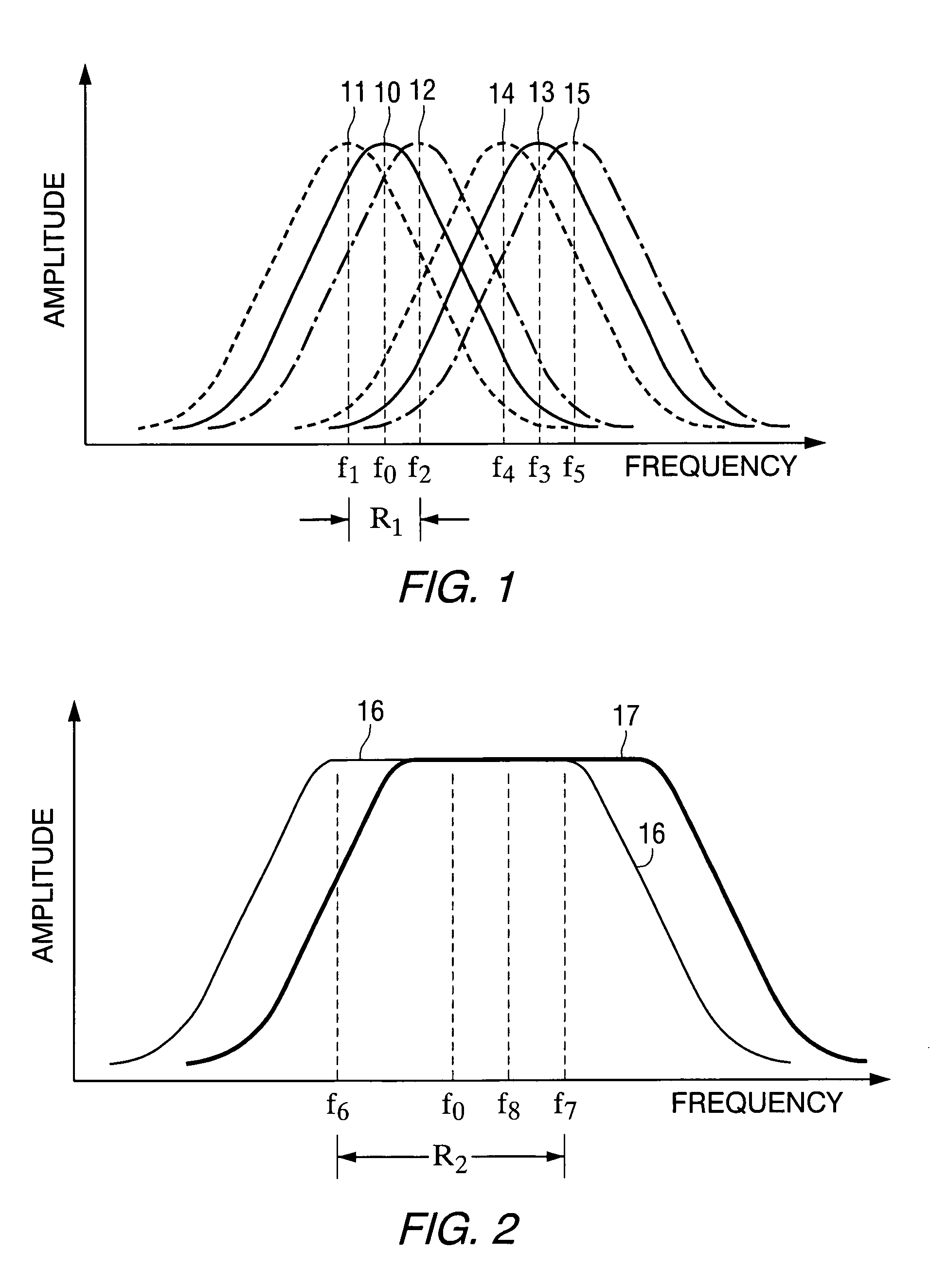
[0018]FIG. 1 illustrates the amplitude vs. frequency response of the signal through the crystal arrangement of a typical crystal oscillator such as described in the aforementioned U.S. Pat. No. 4,851,790. Curve 10, shown solid, has its peak, or maximum transmission, at the nominal resonant frequency of operation f0. This f0 also represents the nominal oscillator operating frequency.

[0019]If a varactor diode circuit is inserted in series with the crystal(s), application of a tuning voltage to the diodes will cause the response of FIG. 1, and the resultant oscillator operating frequency to vary below and above f0 to f1 and f2, shown by curves 11 and 12. The total oscillator tuning range is f2–f1. Due to crystal aging, or other reasons, the operating frequency may drift to a position illustrated by curve 13. At this position the peak of the curve has increased to a frequency of f3 which lies outside the oscillator tuning range, shown as frequency f4 and f5, and curves 14 and 15. Operat...


PUM


Abstract

A crystal oscillator having a crystal filter with multiple crystals in a ladder configuration, resonant at a desired operating frequency. An oscillatory signal loop feedback path includes a voltage controlled phase shifter operable to shift the phase of the signal in the feedback loop in response to an applied control voltage. The feedback loop also includes a loop phase shift circuit to ensure that the feedback signal is a multiple of 360°, and a band pass mode selection circuit for eliminating unwanted frequencies.

Description

BACKGROUND OF THE INVENTION[0001]1. Field of the Invention[0002]The invention in general relates to electronic oscillators and more particularly to a crystal oscillator utilizing a plurality of piezoelectric crystals.[0003]2. Description of Related Art[0004]A crystal oscillator is an electronic circuit that produces electrical oscillations at a particular designed frequency determined by the physical characteristics of one or more crystals, generally of quartz, positioned in the circuit feedback loop.[0005]During operation of the crystal oscillator, the output frequency may drift relative to the designed frequency, necessitating a tuning operation to bring it back. For this purpose a tuning mechanism can be provided. Crystal oscillators are conventionally tuned by inserting a variable reactance circuit in series with the crystal. Electrical tuning is normally accomplished using variable capacitance (varactor) diodes to provide the variable reactance. A typical crystal oscillator uti...

Claims


Application Information

Patent Timeline
IPC IPC(8): H03B5/32
CPCH03B5/366
Inventor DRISCOLL, MICHAEL M.METZGER, KARL M.VALE, CHRISTOPHER R.MATTHEWS, NORMAN G.
Owner NORTHROP GRUMMAN SYST CORP
Why Eureka
Try Eureka