Position detection apparatus and exposure apparatus

a technology of exposure apparatus and detection apparatus, which is applied in the direction of photomechanical apparatus, instruments, printers, etc., can solve the problems of easy swing of the stage, long time required for the swing (variation) of the stage to subside, and errors in alignment mark measurement results

Inactive Publication Date: 2007-01-30
CANON KK
View PDF15 Cites 22 Cited by
  • Summary
  • Abstract
  • Description
  • Claims
  • Application Information

AI Technical Summary

Problems solved by technology

However, when the stage is quickly accelerated and stopped, the entire exposure apparatus may swing, and a long time may be required for swing (variation) of the stage to subside.
As a consequence, the alignment mark measurement result contains errors due to swing of the stage.
However, when the mount system is adjusted to suppress swing caused by quick acceleration and stop of the stage, the stage may readily swing due to the influence of swing of the floor.
As a result, the throughput cannot be improved conventionally.

Method used


Image

  • Position detection apparatus and exposure apparatus
  • Position detection apparatus and exposure apparatus
  • Position detection apparatus and exposure apparatus

Examples


first embodiment

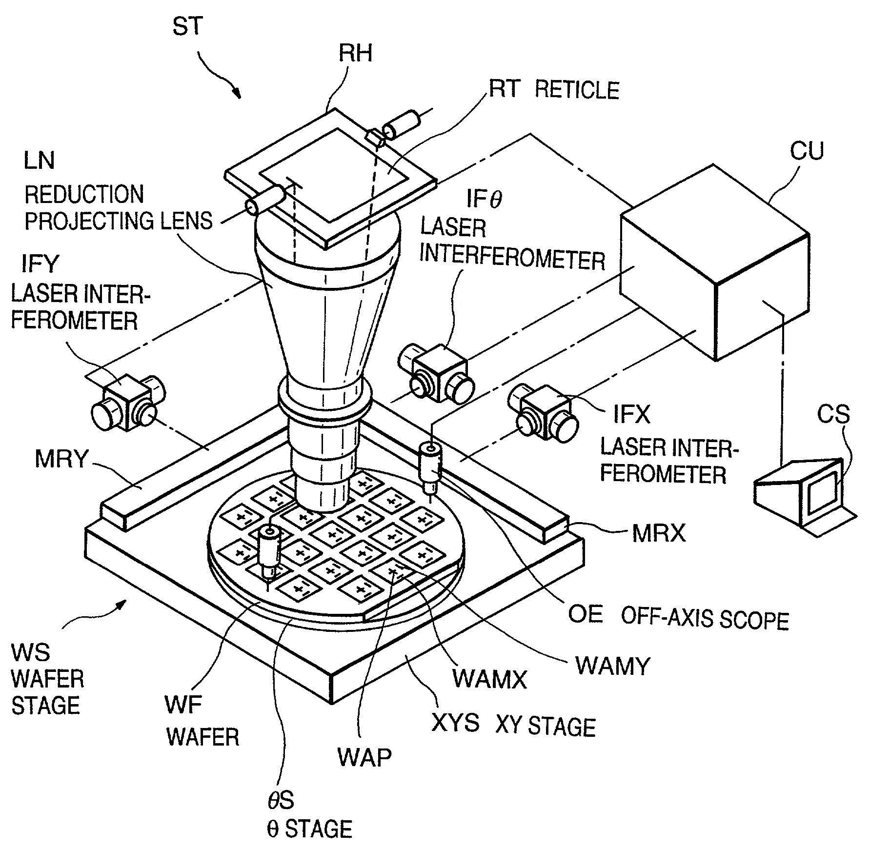
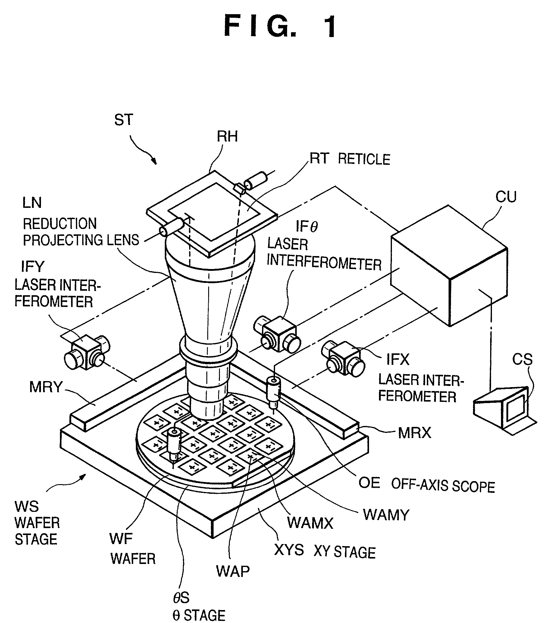
[0052]A projecting exposure apparatus (stepper) ST according to the present invention comprises a reticle holder RH for holding a reticle RT, an off-axis scope OE as an image sensing section for sensing images of alignment marks (to also be simply referred to as marks) WAMX and WAMY on a wafer WF, XY stage XYS and θ stage θs for moving the wafer WF, laser interferometer IFX and mirror MRX for measuring the position or deviation (difference between the target position and actual position) of the XY stage in the X direction, laser interferometer IFY and mirror MRY for measuring the position or deviation of the XY stage in the Y direction, laser interferometer IFθ (mirror MRX is shared) for measuring the rotation amount or deviation of the XY stage, and control unit CU, as shown in FIG. 1.

[0053]On the wafer WF, a number of shots (areas to be exposed) in which the same patterns are formed in the previous exposure and development processes are arrayed. The alignment mark WAMX for measuri...

second embodiment

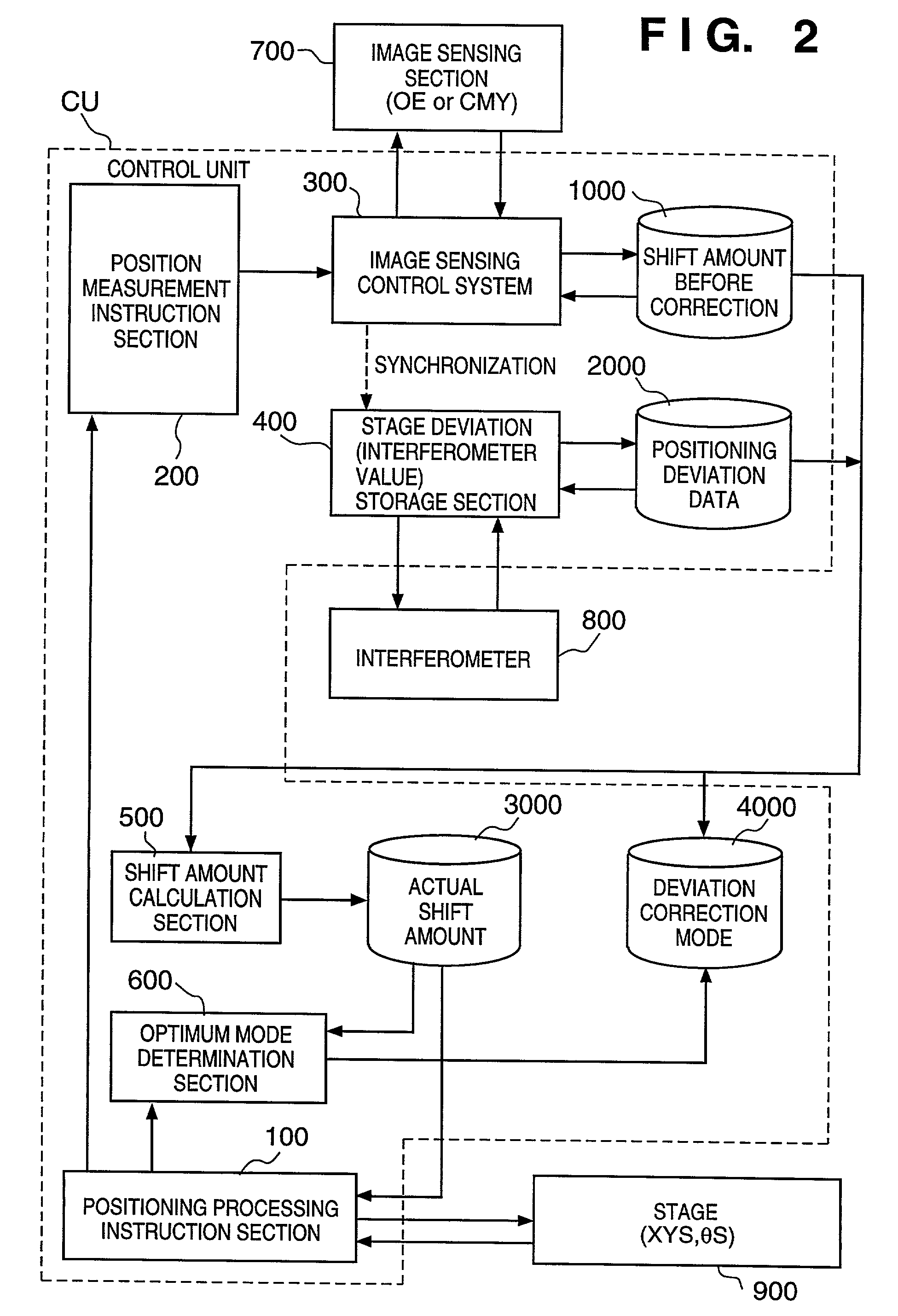
[0075]The actual shift amount of the mark is calculated in accordance with a correction mode specified by information stored in the memory 4000. This correction mode is determined by the optimum mode determination section 600 in advance. Information for specifying the determined correction mode is stored in the memory 4000. An example associated with correction mode determination will be described in the

[0076]In step SA005, it is determined whether the above measurement processing (SA001 to SA004) is ended for all predetermined shots for AGA. If YES in step SA005, the flow advances to step SA006. If NO in step SA005, the flow returns to step SA001.

[0077]In step SA006, the positioning processing instruction section 100 calculates correction amounts to be used for step operation of the stage by AGA on the basis of the information representing the actual shift amount of each mark on the stage, which is stored in the memory 3000.

[0078]Processing in step SA003 of FIG. 4 will be described...

third embodiment

[0142] since the shift amount of a mark on a wafer can be detected while moving the stage, alignment such as global alignment can be performed at a high speed.

[0143]The above embodiments are also preferable for measurement of the position of a mark on a wafer when a predetermined time has elapsed after stopping the stage (for example, after a time in which swing is expected to generally settle down has elapsed). In this case, mark position measurement errors due to vibration of the floor can be prevented.

[0144]According to the above embodiments, the shift amount of a mark from the target position, which is measured by sensing the image of the mark by the image sensing section, is corrected on the basis of the deviation of the stage. With this processing, the actual shift amount of the mark can be obtained.

[0145]According to the above embodiments, since alignment is performed on the basis of the actual shift amount of a mark, alignment accuracy becomes high.

[0146]According to the fir...


PUM

PropertyMeasurementUnit
speedaaaaaaaaaa
areaaaaaaaaaaa
areasaaaaaaaaaa

Abstract

An exposure apparatus includes an image sensing section and image sensing control section for measuring the average position of a mark formed on a wafer during a predetermined observation period before a stage completely stops, an interferometer for measuring any deviation of the stage during the observation period, a stage deviation storage section for storing the measurement result by the interferometer in a memory and calculating the average deviation of the stage on the basis of the measurement result, and a shift amount calculation section for calculating the actual position of the mark, while the stage is at rest, on the basis of the average position of the mark and the average deviation of the stage.

Description

BACKGROUND OF THE INVENTION[0001]1. Field of the Invention[0002]The present invention relates to a position detection apparatus and an exposure apparatus and, more particularly, to a detection apparatus for detecting the position of a mark formed on an object placed on a stage, and an exposure apparatus including the apparatus.[0003]More specifically, the present invention is preferably applied to an apparatus for detecting the relative positional relationship between a pattern on an object such as a wafer and a stage on which the object is placed, or the relative positional relationship between the pattern on the object and a pattern on a mask such as a reticle when the pattern formed on the mask is to be transferred to the object.[0004]The present invention is also preferably applied to an apparatus for manufacturing semiconductor devices such as ICs or LSIs, image sensing devices such as CCDs, display devices such as liquid crystal panels, or devices such as magnetic heads, and f...

Claims


Application Information

Patent Timeline
Patent Type & Authority Patents(United States)
IPC IPC(8): G01B11/00G01B11/14G03B27/32G03C5/00G03F9/00G01B11/03G03F7/20H01L21/027H01L21/68
CPCG03F7/70691G03F9/7096G03F9/70G01B11/03
Inventor KATAYAMA, SHOSHI
Owner CANON KK
Why Eureka
Try Eureka