Low attenuation optical fiber

a low-attenuation, optical fiber technology, applied in the field of optical fibers, can solve problems such as signal degradation, and achieve the effects of low attenuation, low small angle scattering, and low attenuation

Active Publication Date: 2007-01-30
CORNING INC
View PDF4 Cites 33 Cited by
  • Summary
  • Abstract
  • Description
  • Claims
  • Application Information

AI Technical Summary

Benefits of technology

[0016]One advantage of this fiber is that it has low attenuation and low small angle scattering (SAS). Because of the low attenuation and / or low SAS losses, this optical waveguide fiber can either eliminate or reduce the number of signal amplifiers needed for a network, which can reduce the cost of the network.

Problems solved by technology

However, the optical fiber attributes such as attenuation and bend loss contribute to the degradation of the signal.

Method used


Image

  • Low attenuation optical fiber
  • Low attenuation optical fiber
  • Low attenuation optical fiber

Examples


Embodiment Construction

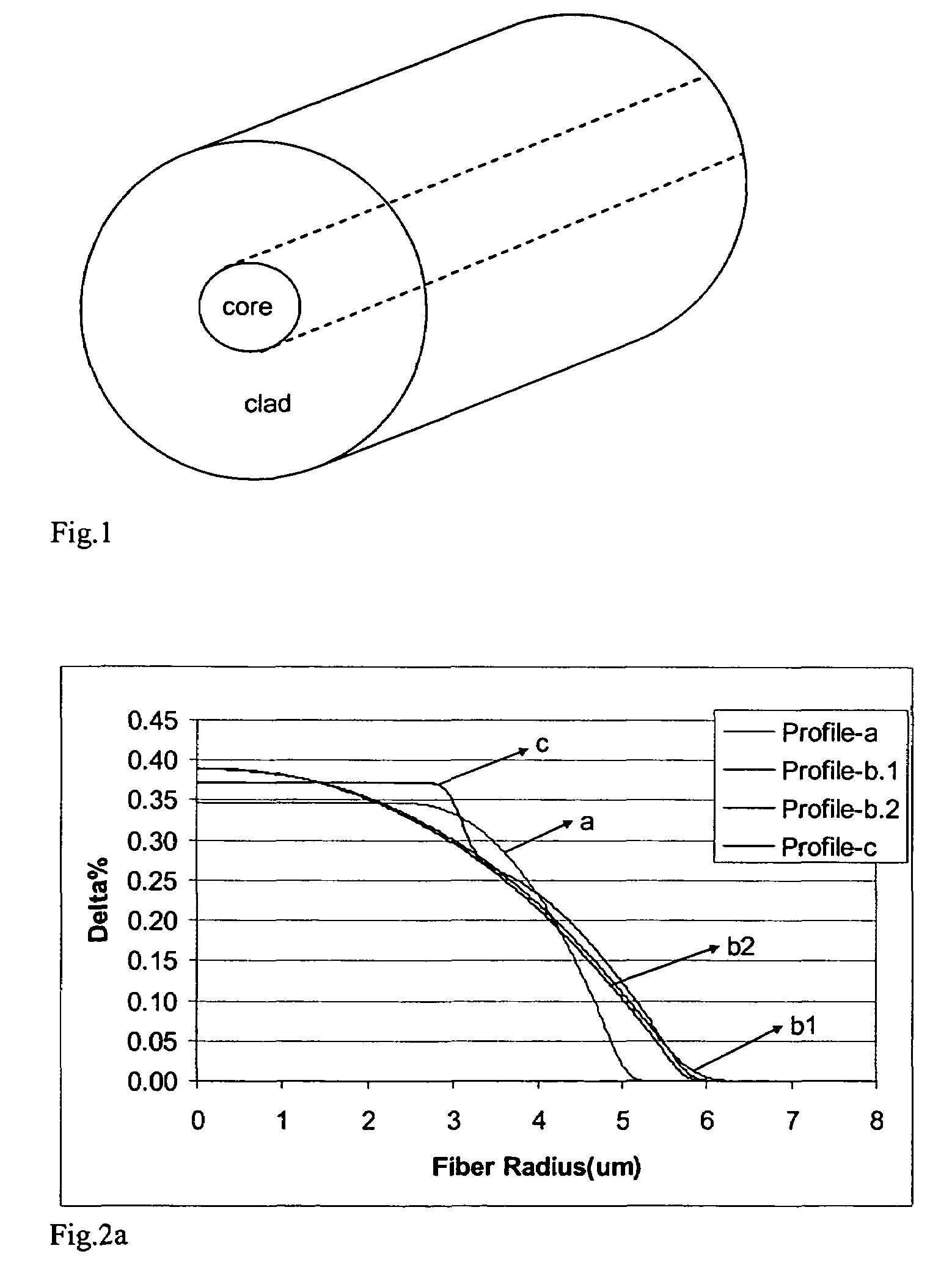
[0024]Reference will now be made in detail to the present preferred embodiments of the invention, examples of which are illustrated in the accompanying drawings. Whenever possible, the same reference numerals will be used throughout the drawings to refer to the same or like parts. One embodiment of the optical fiber waveguide of the present invention is shown in FIG. 1, and is designated generally throughout by the reference numeral 10.

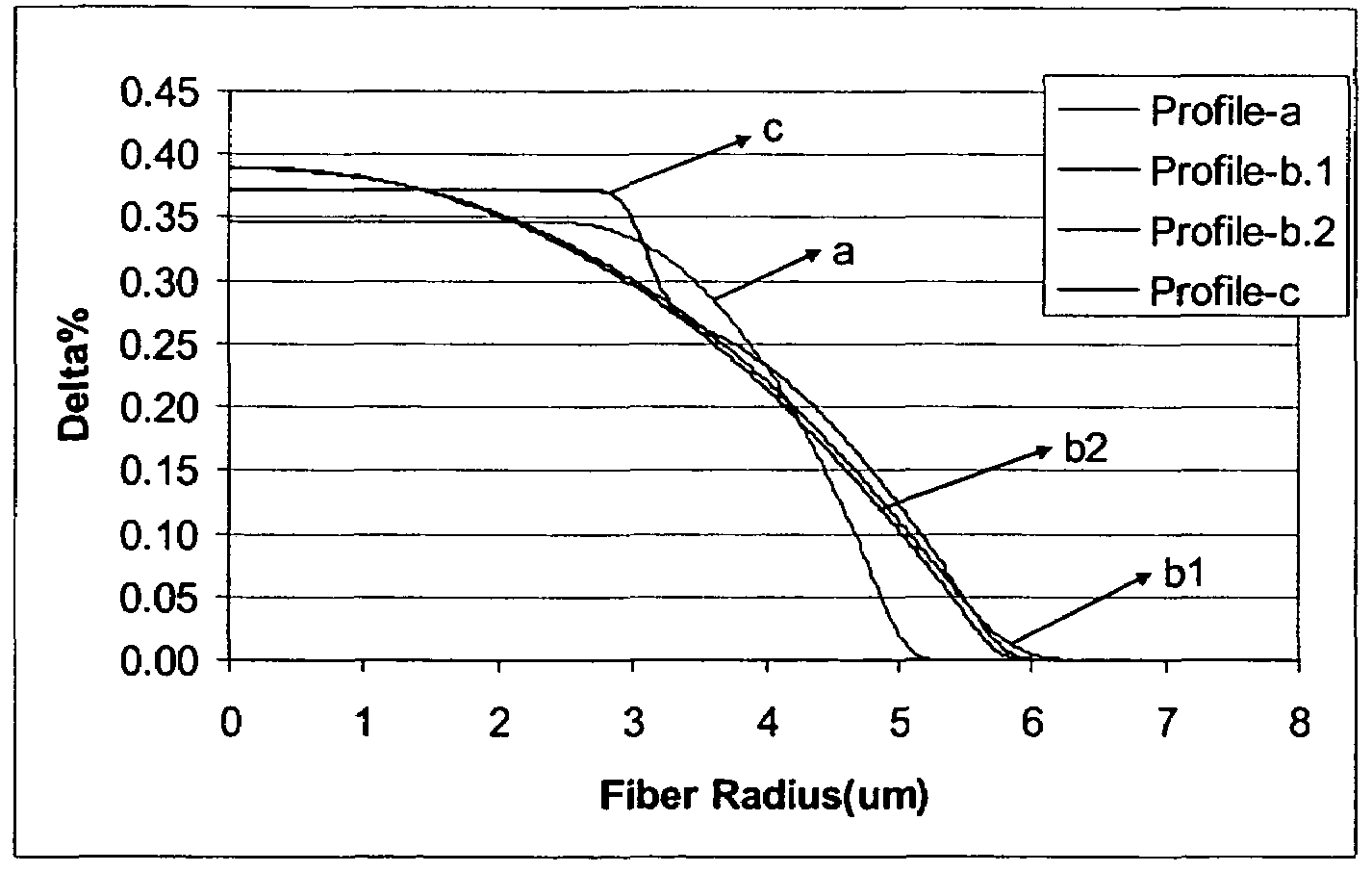
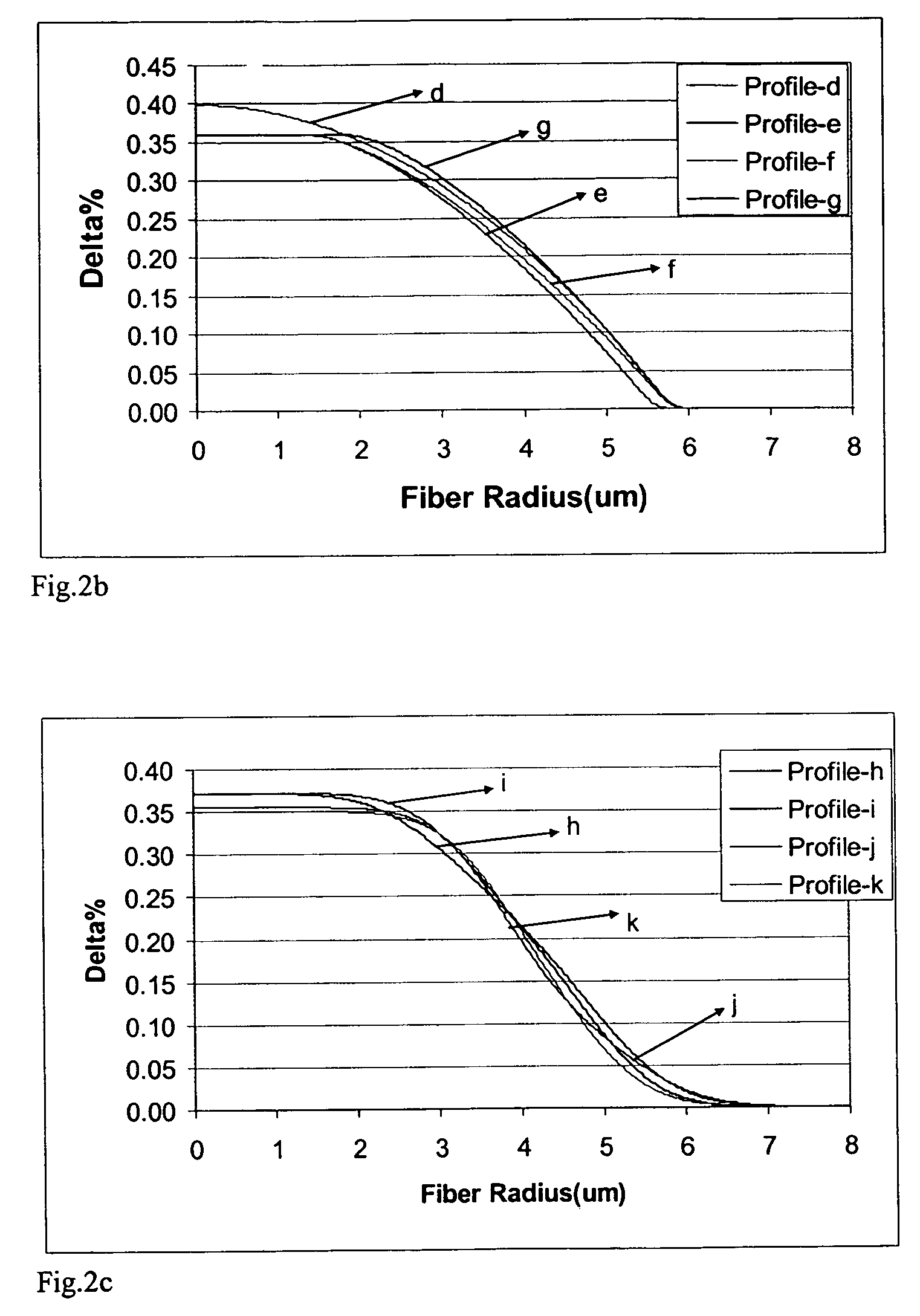
[0025]In accordance with the invention the optical waveguide fiber includes a core 12 and at least one cladding 14 surrounding the core 12. In these exemplary embodiments the cladding 14 is pure silica and the silica core 12 is doped with Ge to obtain the desired change in relative refractive index (3.5–4.2 mole % of Ge). The diameter of the core 12 varies from 9 μm to 16 μm. The outer diameter of the cladding 14 of these exemplary optical fibers 10 is about 125 μm. The exemplary refractive index fiber profiles of these optical waveguide fibers 10 are...


PUM


Abstract

An optical waveguide fiber comprises: (a) a core with a refractive index profile having, a radius, an alpha and a relative refractive index characterized by delta % that varies along the radius; (b) at least one cladding surrounding the core; wherein the alpha is less than 2.5, peak refractive index delta % is between 0.34% and 0.4%, the relative refractive index is less than 0.01% for all radii greater than 7 μm, and this optical waveguide fiber has a mode field diameter MFD at a wavelength of 1310 nm of no more than 9.54 μm, and attenuation less than: (a) 0.329 dB / km at a wavelength of 1310 nm, (b) 0.290 dB / km at a wavelength of 1383 nm, (c) 0.255 dB / km at a wavelength of 1410 nm, and (d) 0.189 dB / km at a wavelength of 1550 nm.

Description

BACKGROUND OF THE INVENTION[0001]1. Field of the Invention[0002]The present invention relates generally to optical fibers, and particularly to optical fibers with low attenuation and low Small Angle Scattering (SAS) loss.[0003]2. Technical Background[0004]Telecommunication systems, for the underground and undersea applications in particular, require optical fiber which is capable of transmitting signals for a long distance without degradation. The appearance of new technologies, such as wavelength division multiplexing (WDM) and high channel speed, makes possible to satisfy the ever-growing demand for network bandwidth. However, the optical fiber attributes such as attenuation and bend loss contribute to the degradation of the signal.[0005]US patent publication 2003 / 0161597 discloses an optical fiber capable of multi mode operation at wavelengths below 1300 nm and single mode operation at wavelengths above 1300 nm. The publication describes that this optical fiber has reduced interm...

Claims


Application Information

Patent Timeline
Patent Type & Authority Patents(United States)
IPC IPC(8): G02B6/02G02B6/028G02B6/036
CPCG02B6/0281
Inventor MATTINGLY, III, WILLIAM BRASHEARMISHRA, SNIGDHARAJ KUMARZHANG, LU
Owner CORNING INC
Why Eureka
Try Eureka