Dry sump type lubrication device for a motorcycle

a lubrication device and motorcycle technology, applied in closed-circuit pressure lubricating systems, cycle equipment, lubrication elements, etc., can solve the problems of reducing the minimum road clearance by as much, reducing the volume of the tank, and affecting the service life of the engine, so as to avoid excessive rise of inside tank pressure and prevent damage to the oil tank

Inactive Publication Date: 2007-02-06
YAMAHA MOTOR CO LTD
View PDF10 Cites 7 Cited by
  • Summary
  • Abstract
  • Description
  • Claims
  • Application Information

AI Technical Summary

Benefits of technology

[0014]According to the present invention, if the amount of lubricating oil returning to the oil tank is too large and the oil tank is filled with the lubricating oil, an excess of the lubricating oil is sent automatically to the four-stroke engine through an overflow passage. Therefore, even if the tank volume is decreased in association with size reduction of the oil tank, excessive rise of the inside tank pressure can be avoided. As a result, damage of the oil tank is prevented, as well as leakage of lubricating oil from the connecting portions between the oil tank and passages.

Problems solved by technology

However, in this arrangement, since the oil tank protrudes downwardly from the crankcase, the minimum road clearance is lowered by as much size as the oil tank.
As a result, in a motorcycle for motocross races in particular, the oil tank might strike against the road surface during running.
However, an oil tank with the size reduced results in a decreased tank volume and a new problem arises as described below.
Therefore, in a condition in which engine speed is low during an idling operation, for example, lubricating oil returning to the oil tank and lubricating oil drawn from the oil tank become ill-balanced and the inside of the oil tank is filled completely with lubricating oil.
In other words, if the amount of lubricating oil returning to the oil tank becomes larger than the amount of lubricating oil drawn from the oil tank, the change in oil quantity cannot be absorbed within the oil tank.
Therefore, the inside pressure of the oil tank rises excessively, which may cause damage of the oil tank or leakage of lubricating oil from the connecting portions between the oil tank and connecting device.

Method used


Image

  • Dry sump type lubrication device for a motorcycle
  • Dry sump type lubrication device for a motorcycle
  • Dry sump type lubrication device for a motorcycle

Examples


Embodiment Construction

[0023]Now, an embodiment of this invention will be described with reference to the drawings.

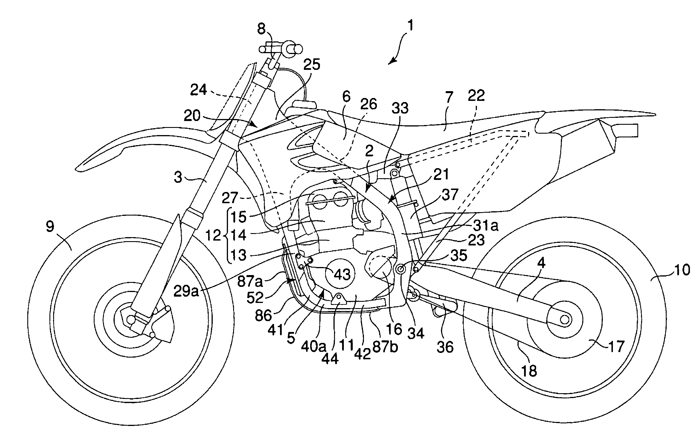
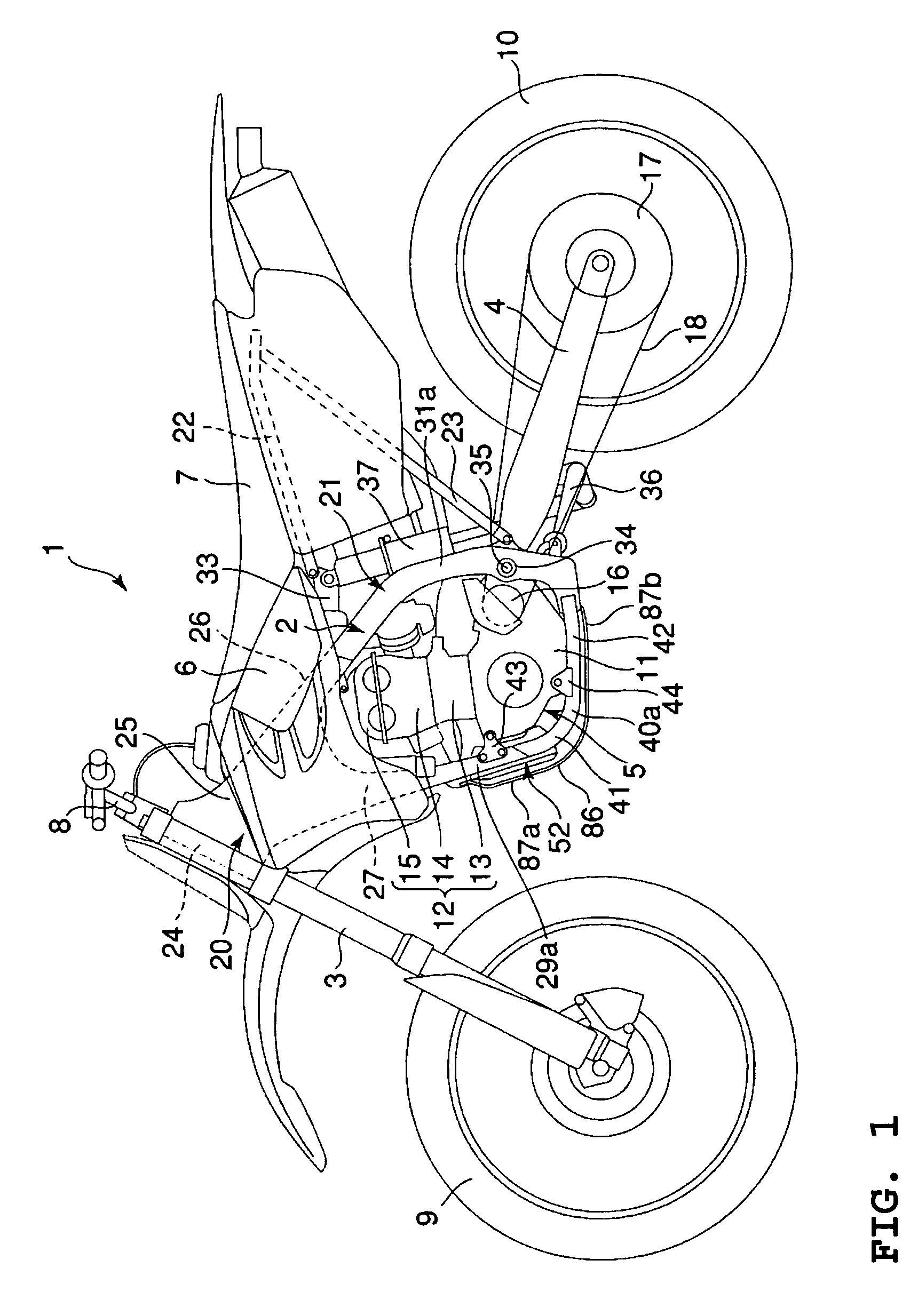
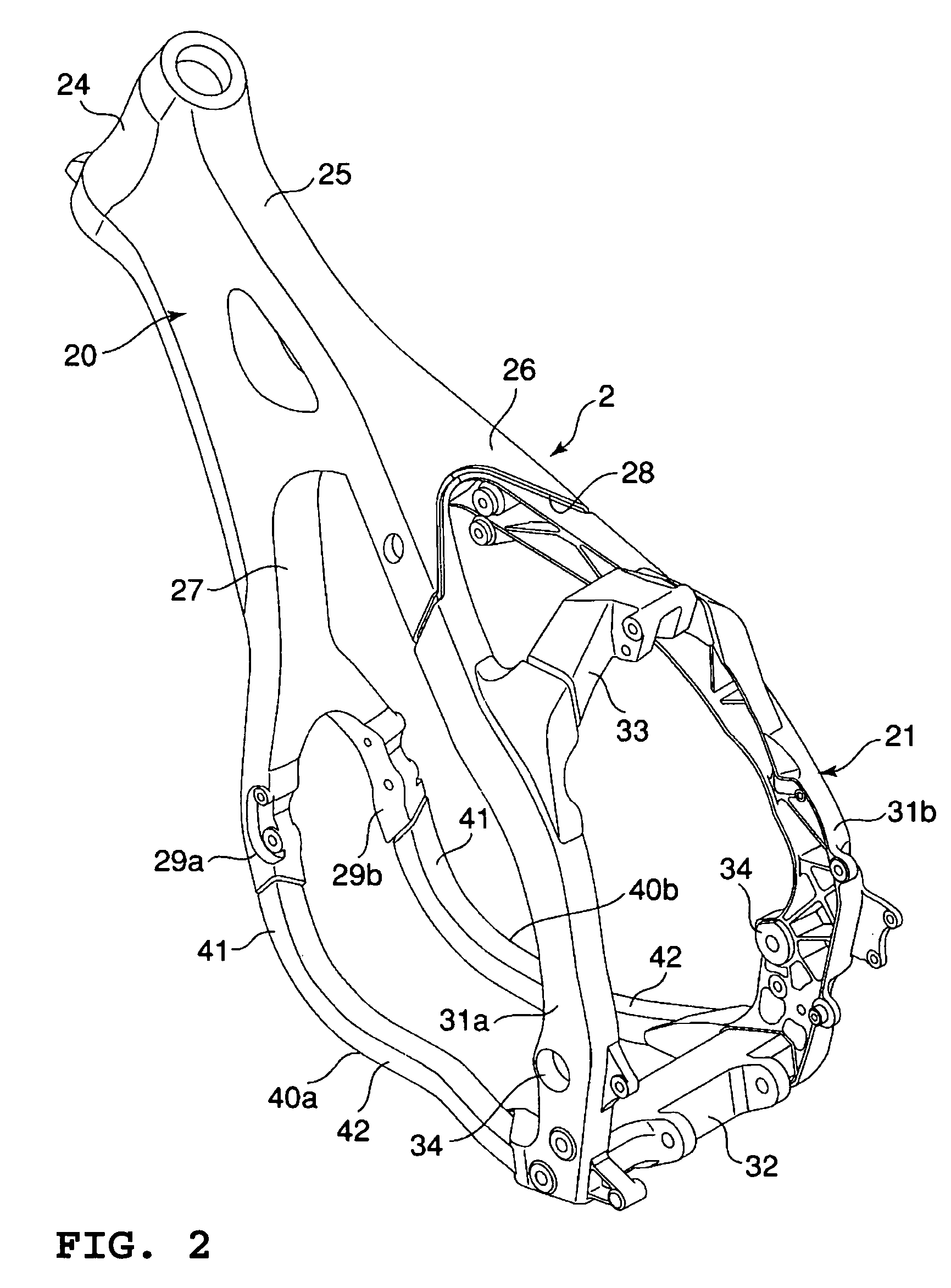
[0024]FIG. 1 shows a motorcycle 1, for example, for motocross races. The motorcycle 1 is provided with a frame 2 of a cradle type. The frame 2 supports a front fork 3; a rear arm 4; a water-cooled, four-stroke, single-cylinder engine 5; a fuel tank 6 and a seat 7.

[0025]The front fork 3 is controlled by a bar handle 8 for steering and supports a front wheel 9. The rear arm 4 extends rearwardly from the frame 2 and supports, at its rear end, a rear wheel 10.

[0026]The engine 5 is provided with a crankcase 11, and a cylinder section 12 standing approximately upright from the crankcase 11. The cylinder section 12 includes a cylinder block 13 connected to the upper surface of the crankcase 11, a cylinder head 14 mounted on the cylinder block 13 at the upper end, and a head cover 15 for covering the upper end of the cylinder head 14. The head cover 15 is formed with a valve drive chamber between the...


PUM


Abstract

A dry sump type lubrication device for a motorcycle includes a four stroke engine having, in a crankcase bottom, a first oil pump for collecting lubricating oil and a second oil pump for delivering lubricating oil. A frame supporting the four-stroke engine and having left and right down tubes running around the crankcase from the crankcase front thereof toward a region therebelow is provided. An oil tank is disposed in a region surrounded by a forward end of the crankcase and the left and right down tubes, a return passage for the lubricating oil collected by the first oil pump to be returned to the oil tank. A feed passage for the lubricating oil returned to the oil tank to be introduced into the second oil pump and an overflow passage for the lubricating oil in the oil tank to be returned to the four-stroke engine are also provided.

Description

BACKGROUND OF THE INVENTION[0001]1. Field of the Invention[0002]This invention relates to a dry sump type lubrication device for a motorcycle with an oil tank disposed in front of a crankcase.[0003]2. Description of Related Art[0004]Recent years, motorcycles for motocross races have made progress in the changeover of their engines to four-stroke systems. Since the motorcycle of this type runs on rough ground of great irregularities, it is necessary to raise the mounting position of the engine to secure a sufficient minimum road clearance. Therefore, a dry sump type four-stroke engine is preferably used without an effective oil reservoir in the bottom of the crank chamber.[0005]The dry sump type four-stroke engine is provided with an oil tank independent from the crankcase, and lubricating oil is forcedly circulated between the oil tank and the crankcase. Specifically, lubricating oil returned to the crankcase after lubrication of engine parts is sent into the oil tank through a firs...

Claims


Application Information

Patent Timeline
Patent Type & Authority Patents(United States)
IPC IPC(8): B62J31/00F01M1/00F01M1/02F01M1/06F01M1/12F01M9/10F01M11/00
CPCF01M1/12F01M2001/126
Inventor MURAMATSU, TAKAYOSHI
Owner YAMAHA MOTOR CO LTD
Why Eureka
Try Eureka