
Method and circuit for digitally correcting the frequency of a signal

Inactive Publication Date: 2007-02-06
INTEL CORP
View PDF12 Cites 11 Cited by
  • Summary
  • Abstract
  • Description
  • Claims
  • Application Information

AI Technical Summary

Benefits of technology

[0012]The invention therefore has as its object to provide a process and a circuit arrangement for digital frequency correction, particularly for use in a transceiver circuit, which produces a very precise frequency correction with a small circuit technology cost.
[0014]An exemplary embodiment of the present invention includes an CORDIC (Coordinate Rotation Digital Computer) algorithm for digital frequency correction of a signal. Namely, a frequency and phase correction can be carried out relatively simply using the CORDIC algorithm. The CORDIC algorithm can be carried out with a small circuit technical cost, so that costs of a circuit based on the CORDIC algorithm and an inexpensive oscillator are smaller than the costs of a compensated oscillator.

Problems solved by technology

Particularly because of production tolerances, temperature fluctuations, and supply voltage fluctuations, undesired fluctuations of the reference frequency can occur.
In order to counteract the undesired fluctuations, expensive and high quality oscillators are, for example, used in the transceiver circuits, to produce a very stable reference frequency, i.e., an oscillator which is precise and free from fluctuation.
However, the AFC loops are disadvantageous in that the AFC loops are expensive and very costly in circuit technology.
However, particularly in such products, no excessive fluctuation of the reference frequency can be tolerated.
The frequency correction according to the above equation may be calculated using digital multipliers and coefficient tables for a sine and cosine functions; which demands, though, a very high circuit technology cost which makes such a solution expensive and costly.
In particular, when embodied as an integrated circuit, this solution requires a large chip surface and is, therefore, very expensive.

Method used


Image

  • Method and circuit for digitally correcting the frequency of a signal
  • Method and circuit for digitally correcting the frequency of a signal
  • Method and circuit for digitally correcting the frequency of a signal

Examples


Embodiment Construction

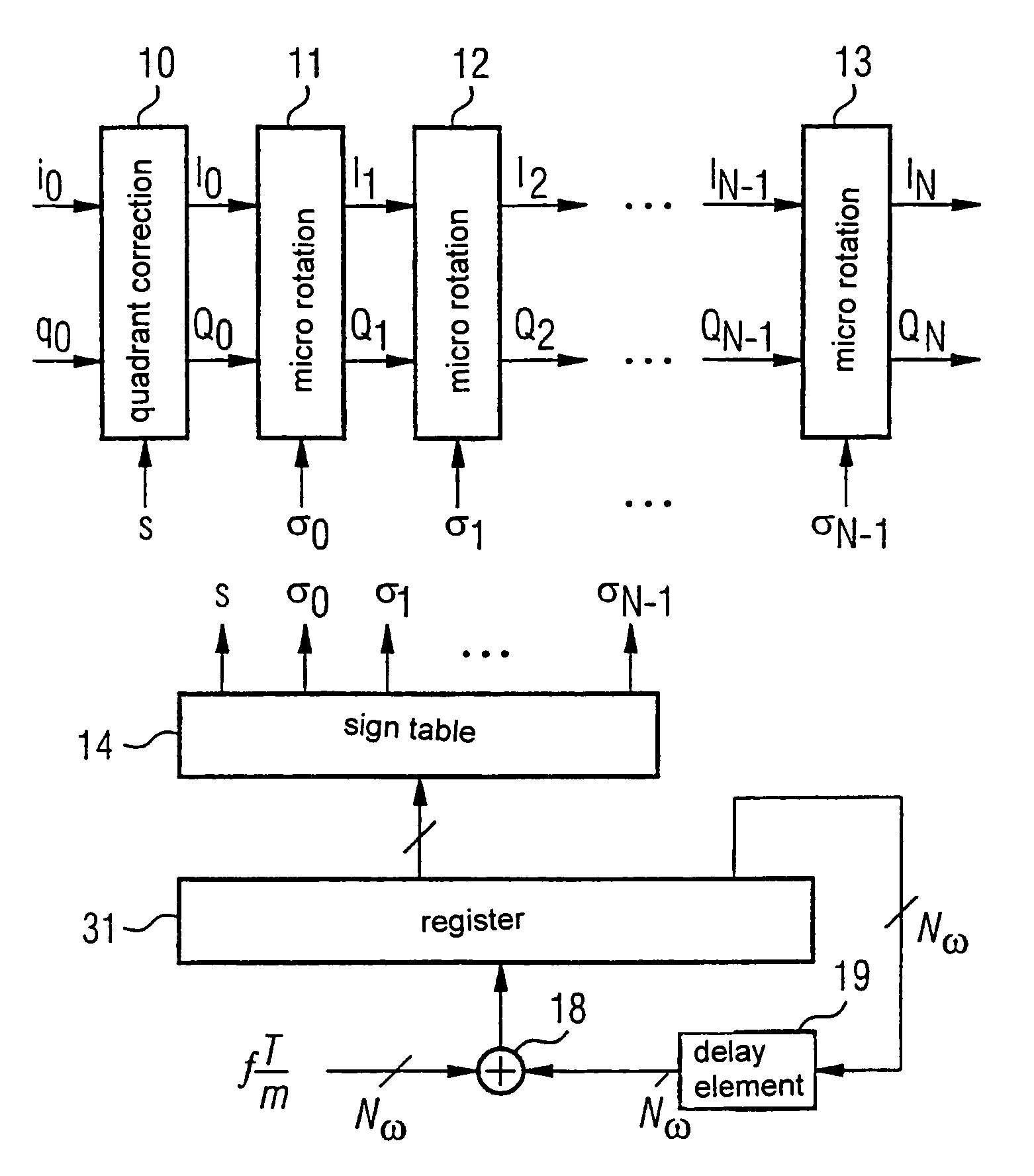
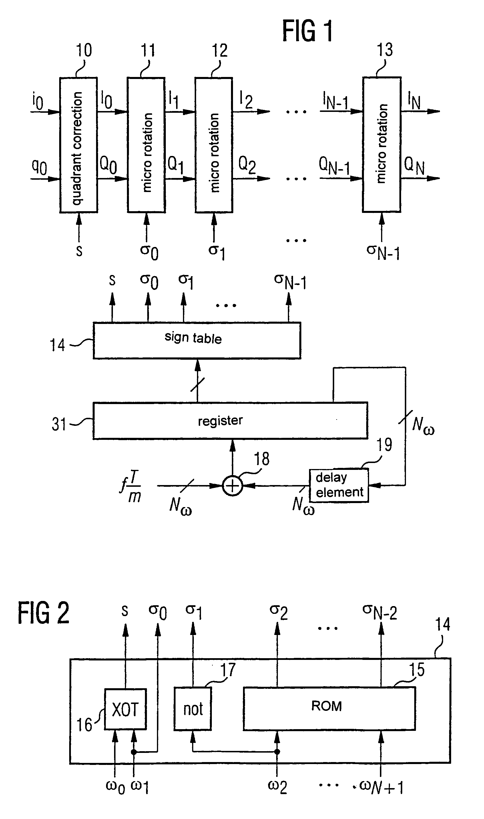
[0035]In FIG. 1, sampling values i0 and q0 of an in-phase or quadrature components of a complex baseband signal x(k) are supplied to a quadrant correction block 10, where k denotes discrete sampling times. The quadrant correction block 10 causes a pointer represented by the baseband signal x(k) to lie in a first or fourth quadrant of a complex in-phase / quadrature I / Q plane. Namely, if the pointer lies in a second or third quadrant, CORDIC algorithm does not work correctly. As already described, the in-phase and quadrature components have to be respectively multiplied by −1 if the pointer is situated in the second or third quadrant of the complex I / Q plane.

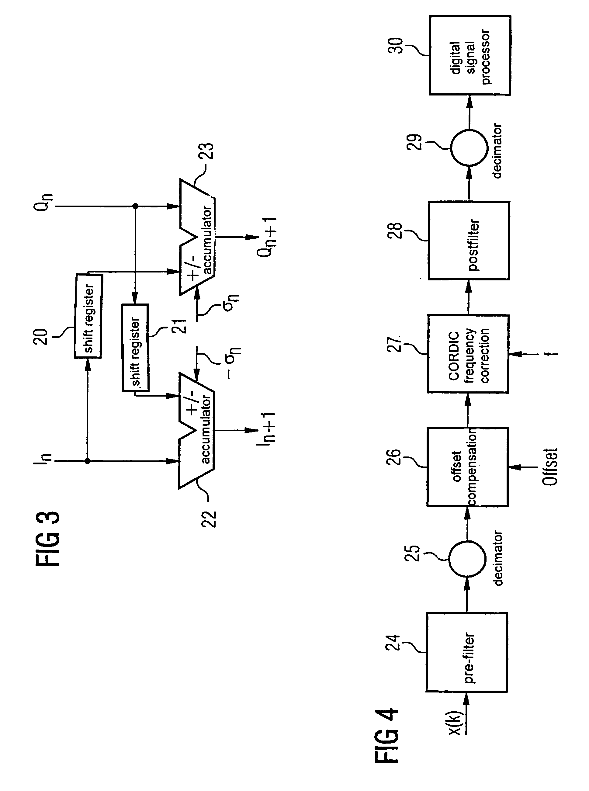
[0036]N micro-rotation blocks in sequence follow the quadrant correction block 10 although three of these blocks, 11, 12, 13, are shown, a one of ordinary will appreciate that more blocks may be implemented. Each micro-rotation block calculates a step of the CORDIC algorithm, i.e., rotates the pointer represented by the in-phase an...


PUM


Abstract

A method and a circuit for the digital correction of a frequency of a signal, especially for use in a transmitter / receiver circuit include rotating a signal “pointer” (i0, q0) using a CORDIC algorithm, through a predetermined angle in a complex I / Q plane corresponding to a correction frequency. The CORDIC algorithm includes micro-rotation blocks corresponding to N stages, and a character table and a register.

Description

CROSS-REFERENCE TO RELATED APPLICATIONS[0001]This application claims the benefit of and priority to International Application PCT / DE00 / 03601, filed October 11, and German Patent Application GR 99 P 5026, filed Oct. 11, 1999, the contents of each of which are incorporated herein.BACKGROUND OF THE INVENTION[0002]1. Field of the Invention[0003]The invention relates to a process and a circuit arrangement for digital frequency correction of a signal, in particular for use in a transceiver circuit, by sampling the signal with a predetermined cycle and processed using an N-step CORDIC algorithm so that a frequency of the signal is altered by a predetermined frequency.[0004]2. Description of the Related Art[0005]In transceiver circuits, local oscillators are used to produce a reference frequency. Particularly because of production tolerances, temperature fluctuations, and supply voltage fluctuations, undesired fluctuations of the reference frequency can occur. The undersigned fluctuations o...

Claims


Application Information

Patent Timeline
IPC IPC(8): H04L27/22H04L27/38G06F7/48H04L7/00H04L27/00
CPCG06F7/4818H04L27/0014H04L2027/0063H04L2027/003H04L2027/0018
Inventor YANG, BINBUCH, STEFFEN
Owner INTEL CORP
Learn More