Method and apparatus for performing sub-picture level splicing based on interrupts

a technology of sub-picture level and interrupts, applied in the field of communication systems, can solve the problems of requiring a significant amount of memory, unable to acquire the current database of programming information in the terminal, and unable to meet the current programming information requirements of the terminal

Active Publication Date: 2007-02-06
COX COMMUNICATIONS
View PDF5 Cites 20 Cited by
  • Summary
  • Abstract
  • Description
  • Claims
  • Application Information

AI Technical Summary

Benefits of technology

[0006]The invention provides techniques to effectuate splicing at sub-picture level. In one aspect, splicing is effectuated via an interrupt generated after each splice has occurred. The interrupt may be generated by either the hardware designated to perform splicing or other peripheral hardware. The interrupt may be provided to a controller, which then performs the necessary processing to effectuate the next splice (e.g., load a new PID value for the next splice into the hardware register). This interrupt driven splicing scheme eliminates the need for cycle-intensive polling of the splicing hardware to determine whether or not a splice has been performed.

Problems solved by technology

Unfortunately, the existing program guides have several drawbacks.
First, these guides tend to require a significant amount of memory at the set top terminal.
Second, the terminals may be very slow to acquire the current database of programming information when they are turned on for the first time or are subsequently restarted (e.g., a large database may be downloaded to a terminal using only a vertical blanking interval (VBI) data insertion technique).
Such slow database acquisition may disadvantageously result in out of date information or, in the case of services such as pay-per-view (PPV) or video-on-demand (VOD), limited scheduling flexibility for the information provider.
Third, the user interface of existing program guides do not usually look like a typical television control interface; rather the user interface looks like a 1980's style computer display (i.e., having blocky, ill-formed text and / or graphics).

Method used


Image

  • Method and apparatus for performing sub-picture level splicing based on interrupts
  • Method and apparatus for performing sub-picture level splicing based on interrupts
  • Method and apparatus for performing sub-picture level splicing based on interrupts

Examples


Embodiment Construction

A. System

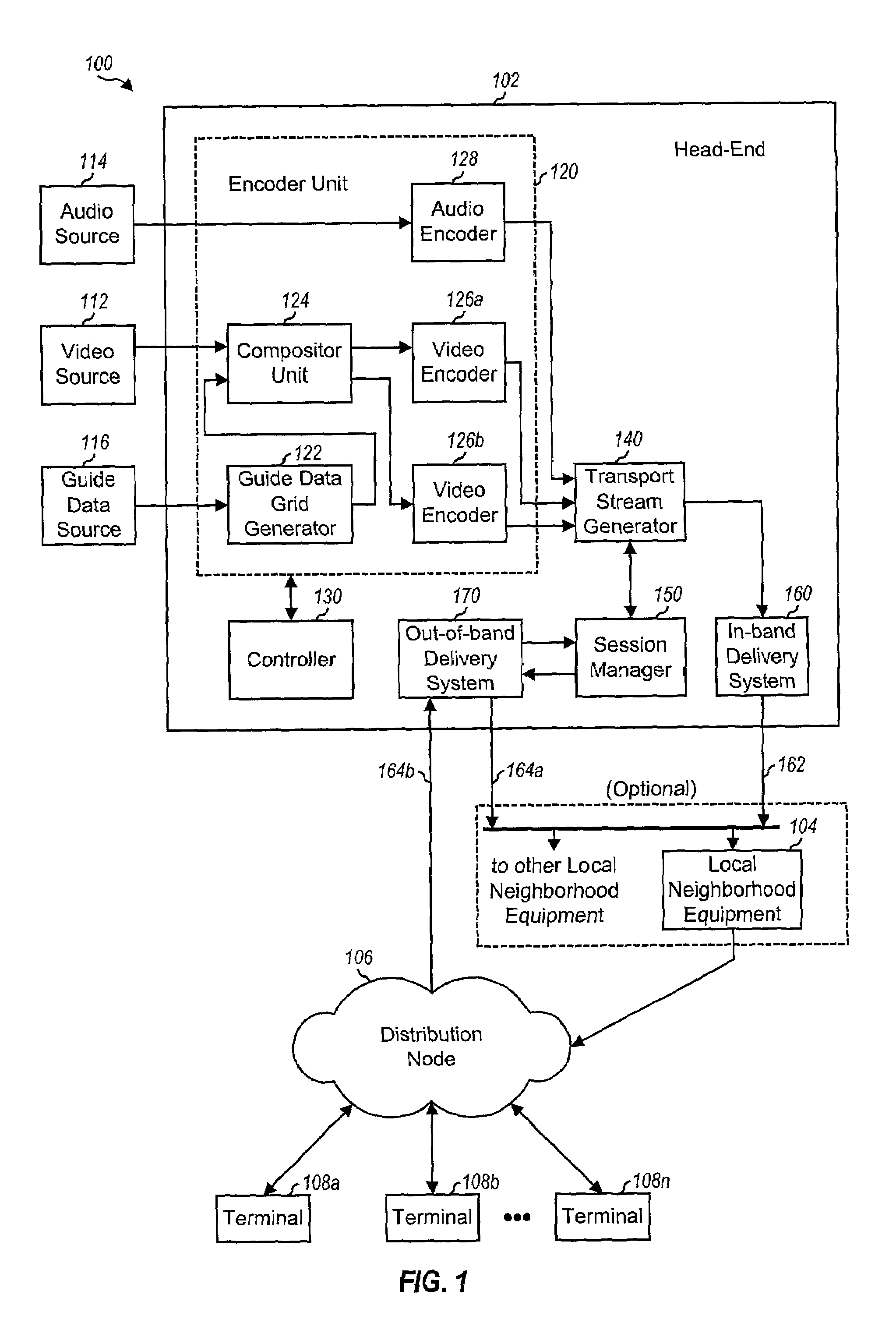
[0021]FIG. 1 is a block diagram of an embodiment of an information distribution system 100 that can be used to provide interactive program guide (IPG) and is capable of implementing various aspects of the invention. Distribution system 100 includes a head-end 102, (optional) local neighborhood equipment (LNE) 104, one or more distribution nodes 106 (e.g., a hybrid fiber-coax network), and a number of terminals 108 (e.g., set top terminals). Each LNE 104 may serve one or more distribution nodes 106, and each distribution node 106 is typically associated with a respective neighborhood that includes a number of terminals 108.

[0022]Head-end 102 produces a number of digital streams that contain encoded information in (e.g., MPEG-2) compressed format. These digital streams are then modulated using a modulation technique that is compatible with a communication channel 162 that couples head-end 102 to LNE 104 and / or distribution node 106.

[0023]In distribution system 100, program st...


PUM


Abstract

Techniques to effectuate splicing at sub-picture level. In one aspect, splicing is effectuated via an interrupt generated after each splice has occurred. The interrupt may be generated by either the hardware designated to perform splicing or other peripheral hardware. The interrupt may be provided to a controller, which then performs the necessary processing to effectuate the next splice (e.g., load a new PID value for the next splice into the hardware register). The interrupts required for splicing may be generated in various manners, and typically depends on the specific design of the splicing and/or peripheral hardware. In one simple design, the splicing hardware generates an interrupt after each splice. Other mechanisms may also be used to generate the interrupt. For example, (e.g., scrambled audio) packets may be inserted into a transport stream and used to cause the hardware to generate an interrupt each time the packet is detected.

Description

BACKGROUND OF THE INVENTION[0001]The present invention generally relates to communication systems. More specifically, the invention relates to techniques to perform sub-picture level splicing based on interrupts.[0002]Over the past few years, the television industry has seen a transformation in a variety of techniques by which its programming is distributed to consumers. Cable television systems are doubling or even tripling system bandwidth with the migration to hybrid fiber coax (HFC) cable plant. Direct broadcast satellite (DBS) systems have also emerged as a viable alternative to customers unwilling to subscribe to local cable systems. A variety of other approaches have also been attempted, which focus primarily on high bandwidth digital technologies, intelligent two-way set top terminals, or other methods to try to offer services differentiated from those of standard cable and over-the-air broadcast systems.[0003]With the increase in bandwidth, the number of programming choices...

Claims


Application Information

Patent Timeline
Patent Type & Authority Patents(United States)
IPC IPC(8): H04N5/93H04N5/44H04N5/445H04N5/45
CPCH04N5/4401H04N5/44543H04N21/42692H04N21/4312H04N21/845H04N21/434H04N21/4351H04N21/443H04N21/482H04N21/6543H04N21/4314H04N5/45H04N21/426H04N21/47
Inventor EDMONDS, JEREMY S.COMITO, JOHN P.
Owner COX COMMUNICATIONS
Why Eureka
Try Eureka