
Distributed computing system architecture

a computing system and distributed computing technology, applied in the field of distributed computing system architectures, can solve the problems of high maintenance costs, system complexity never as simple, and duplication of code that had a severe impact on maintenan

Active Publication Date: 2007-02-06
CHARLES SCHWAB & CO INC
View PDF19 Cites 71 Cited by
  • Summary
  • Abstract
  • Description
  • Claims
  • Application Information

AI Technical Summary

Benefits of technology

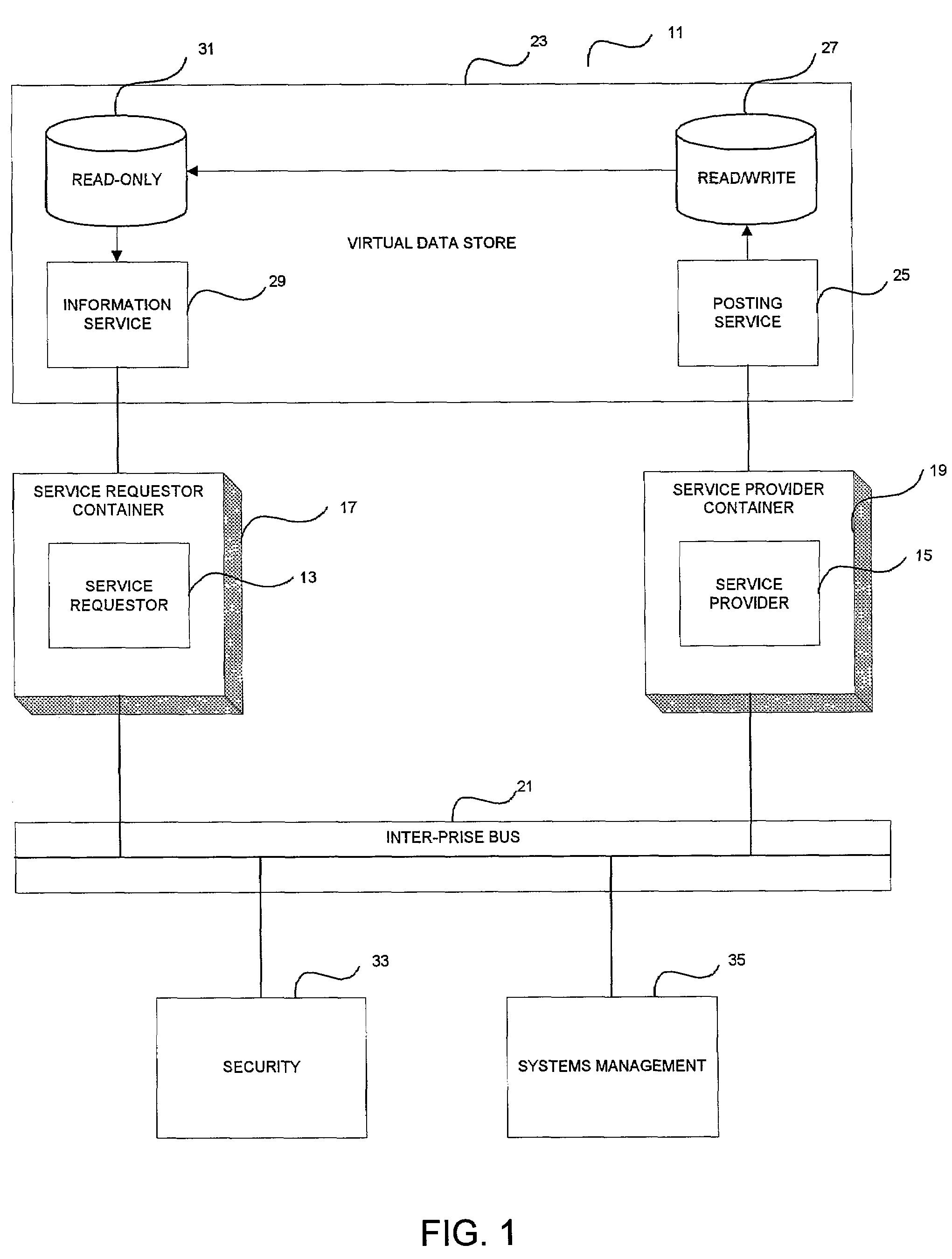
[0017]A container is a component that hides the details of asynchronous messaging and platform dependencies from the business application code of the service. According to the present invention, there are two types of containers, i.e., service requester containers and service provider containers. A service requester container hides details of making a request to the inter-prise bus either to request a service or publish an event. From the perspective of the application residing within the service requester container, the request is a simple call. A service provider container hides details of servicing the request. From the perspective of the application residing in the service provider container, the application sees itself as being invoked locally. The two-container model of the present invention makes programming asynchronous service applications as easy as programming synchronous ones.

Problems solved by technology

In practice, these systems were never as simple as the architectural diagrams made them out to be.
They generated islands of computing, each with incompatible services and clusters of inaccessible data.
This led to a spider's web of interconnected activity and ensured that little problems at one end of the network became large problems throughout the network.
This duplication of code had a severe impact on maintenance because finding and fixing redundant modules was costly.
The impact on extensibility was also serious because it was difficult to change distributed system integration functions.
For many industries, the first generation model created little customer value.
The first generation companies did not deliver real-time products electronically.
Prior to the Internet, old-line financial institutions monopolized access to information.
They turned the resulting customer ignorance about products and performance into profits.
Data belongs to a particular business and that business determines its location, which forces accessing applications to choose between deployment on that same platform or inferior performance.
Once the choice of client or server is made, deployment changes typically result in application changes or rewrites.
Because services are coupled to clients, change management is difficult.
They are also error-prone, often unmanageable, and generally inflexible.
Normally, change implies instability and unavailability.
Moreover, the current models are inflexible.

Method used


Image

  • Distributed computing system architecture
  • Distributed computing system architecture
  • Distributed computing system architecture

Examples


Embodiment Construction

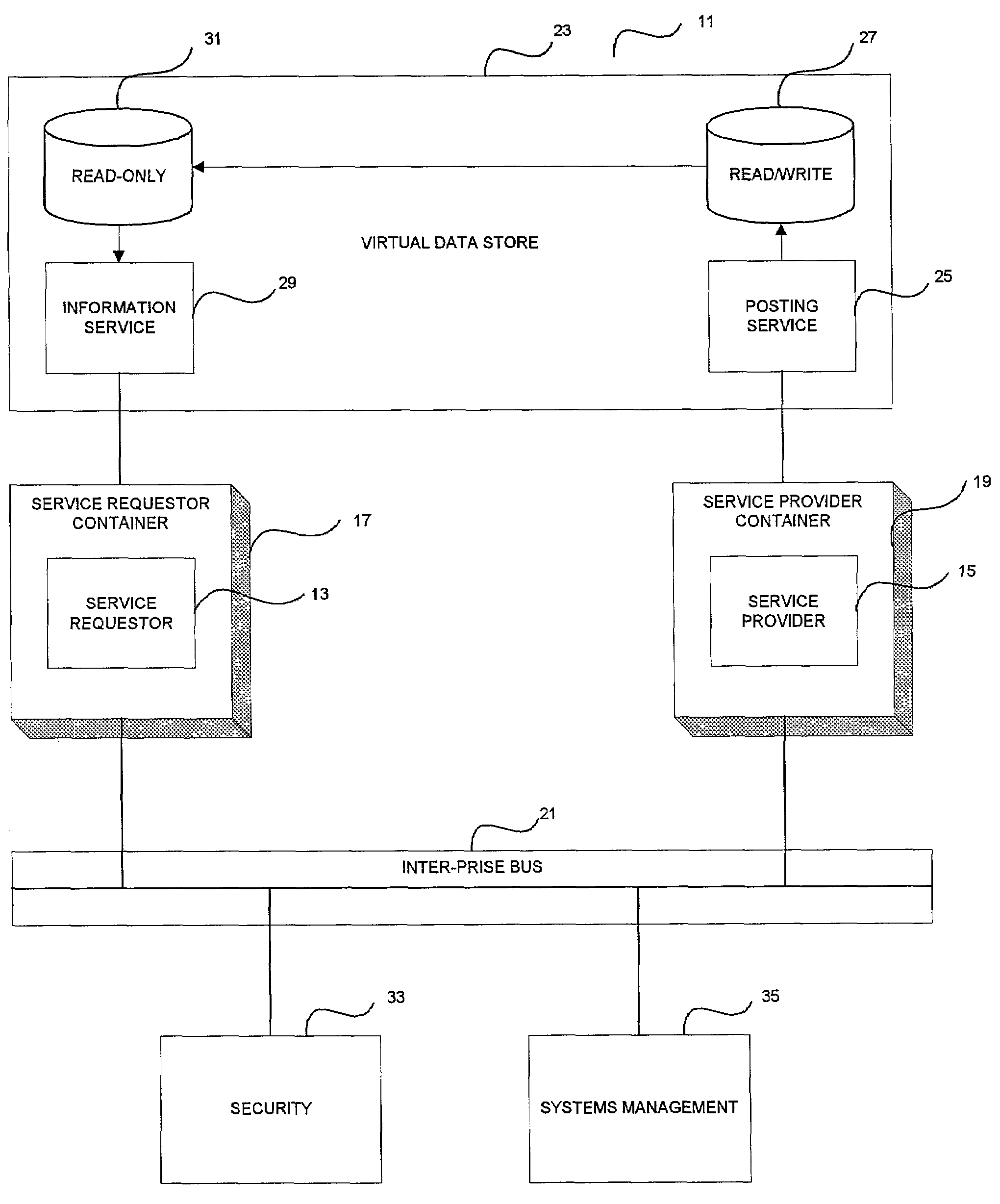
[0034]Referring now to the drawings, and first to FIG. 1, a block diagram of an inter-prise operating system according to the present invention is designated generally by the numeral 11. According to the present invention, asynchronous services, such as a service requester 13 and a service provider 15, reside in containers 17 and 19, respectively. As will be explained in detail hereinafter, containers 17 and 19 simplify the programming of applications by providing a way of naturally invoking services according to a processing model and provide an environment in which services may run according to a services model.

[0035]Services 13 and 15 are linked by an inter-prise bus 21, which handles messaging between requestors 13 and providers 15. According to the present invention, a particular application can be either a service requester or a service provider.

[0036]Services use data from a virtual data store 23. As will be explained in detail hereinafter, virtual data store 23 includes a po...


PUM


Abstract

A computing system architecture is based upon a peer-to-peer, asynchronous model. The architecture specifies a set of infrastructure facilities that comprise an inter-prise operating system. The inter- prise operating system provides all the facilities that make application coding as easy in the peer-to-peer asynchronous model as it is in a hierarchical, synchronous model. Services, which reside in containers, are linked asynchronously by an inter-prise bus and use data from a virtual data store.

Description

CROSS-REFERENCE TO RELATED APPLICATION[0001]The present application claims the benefit of U.S. Provisional Application Ser. No. 60 / 271,353, filed Feb. 22, 2001, titled COMPUTING SYSTEM ARCHITECTURE.FIELD OF THE INVENTION[0002]The present invention relates generally to the field of distributed computing system architectures. More particularly, the present invention provides a computing system architecture in which asynchronous services, which reside in containers, are linked by an inter-enterprise system bus, and use data from a virtual data store. The computing system architecture of the present invention finds particular application in the field of electronic commerce.DESCRIPTION OF THE PRIOR ART[0003]Currently, a substantial amount of business is conducted using electronic commerce. There have been several phases in the development of electronic commerce. In each of these phases, more flexibility has been added to the way systems are constructed. Additionally, with each phase, the...

Claims


Application Information

Patent Timeline
Patent Type & Authority Patents(United States)
IPC IPC(8): G06F15/16G06F3/00
CPCG06F9/546H04L12/1859H04N21/266H04N21/2668G06F2209/547
Inventor GOLDSTEIN, NEAL L.RICHARDS, ADAM J.SHERR, DAVIDLEVY, DAVIDMULLINS, CHALON G.
Owner CHARLES SCHWAB & CO INC
Learn More