Hydraulic crowd control mechanism for a mining shovel

a technology of crowd control and mining shovel, which is applied in the direction of mechanical equipment, mechanical machines/dredgers, servomotors, etc., can solve the problem of preventing a quick response to operator inputs, and achieve the effect of improving response time and responding quickly to operator inputs

Active Publication Date: 2007-02-13
CATERPILLAR GLOBAL MINING LLC
View PDF8 Cites 30 Cited by
  • Summary
  • Abstract
  • Description
  • Claims
  • Application Information

AI Technical Summary

Benefits of technology

[0007]The present invention provides a hydraulic crowd control mechanism that responds quickly to operator inputs. In one embodiment, the crowd control mechanism includes an extendible dipper handle having an extended position and a retracted position. A double acting hydraulic cylinder having an extendible ram has one of the cylinder and the ram fixed to the dipper handle and the other of the cylinder and the ram is stationary relative to the dipper handle. At least one of the cylinder and the ram have at least one of a blind end port and a rod end port, and at least one of the cylinder and the ram have the other of the blind end port and the rod end port, wherein hydraulic fluid flowing into the cylinder through the blind end port urges the ram toward an extended position to extend the dipper handle, and hydraulic fluid flowing into the rod end port urges the ram toward a retracted position to retract the dipper handle. Hydraulic fluid flowing into and out of the cylinder is directly controlled by one or more pilot operated poppet valves. At least one of the pilot operated poppet valves is controlled by a spool valve disposed in the pilot line of the poppet valves to improve the response time to operator inputs over a spool valve directly controlling the flow of hydraulic fluid into and out of the cylinder.

Problems solved by technology

Unfortunately, in the prior art, the volume of hydraulic fluid necessary to control the crowd of a mining shovel dipper handle prevents a quick response to operator inputs compared to the other crowd mechanisms because of the mass of the spools in control valves used to control the flow of the hydraulic fluid.

Method used


Image

  • Hydraulic crowd control mechanism for a mining shovel
  • Hydraulic crowd control mechanism for a mining shovel
  • Hydraulic crowd control mechanism for a mining shovel

Examples


Embodiment Construction

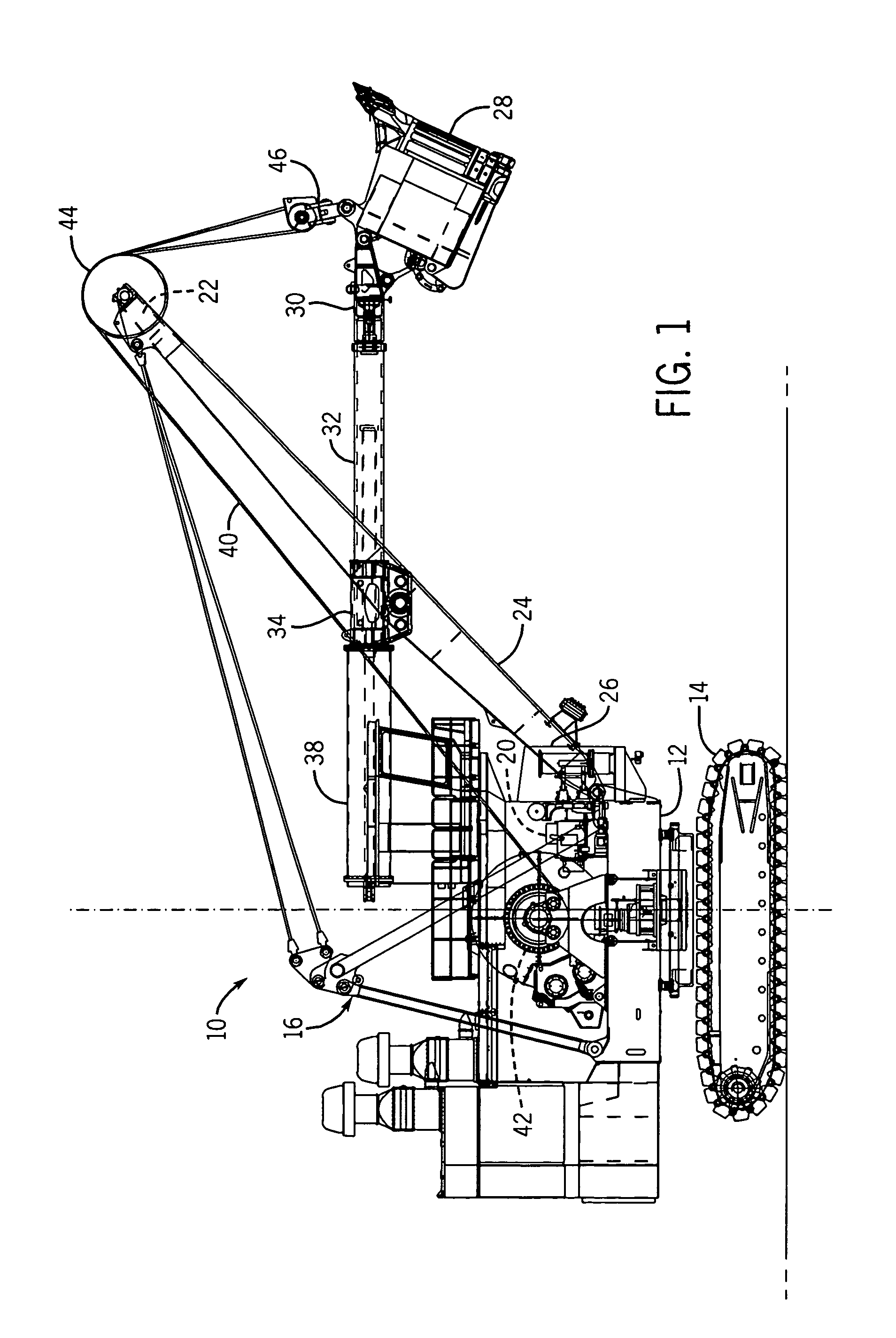
[0017]Referring to FIGS. 1–5, a mining shovel 10 includes a turntable 12 mounted on a crawler truck 14, and supporting an A-frame 16 and a cab 18. The cab houses a power unit 20, control equipment, and operator. The control equipment includes an electrical control system that operates the mining shovel components in response to inputs from the operator and automatic devices, such as limit switches, pressure switches, and temperature switches, and the like. The operator can provide inputs from within the cab through manually operable devices, such as a joystick, lever, foot pedals, rocker switches, computer keyboard, touch pads, and the like.

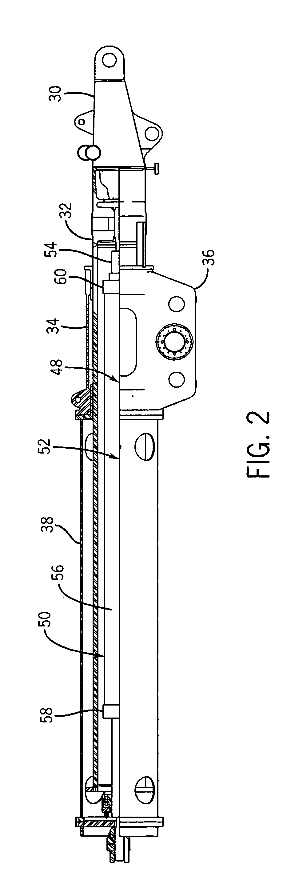
[0018]The A-frame 16 supports a top end 22 of a boom 24, a bottom end 26 of the boom 24 being supported by the turntable 12. A dipper 28 is mounted on the front end 30 of a dipper handle 32 which is slidably supported in a saddle block 34 mounted in the boom 24. The saddle block includes a yoke 36 and a support frame 38 which projects rearwardly ...


PUM


Abstract

A crowd control mechanism for a power shovel includes an extendible dipper handle having an extended position and a retracted position. A double acting hydraulic cylinder having a an extendible ram has one of the cylinder and the ram fixed to the dipper handle and the other of the cylinder and the ram is stationary relative to the dipper handle. At least one of the cylinder and the ram have at least one of a blind end port and a rod end port, and at least one of the cylinder and the ram have the other of the blind end port and the rod end port, wherein hydraulic fluid flowing into the cylinder through the blind end port urges the ram toward an extended position to extend the dipper handle, and hydraulic fluid flowing into the rod end port urges the ram toward a retracted position to retract the dipper handle. Hydraulic fluid flowing into and out of the cylinder is controlled by one or more pilot operated poppet valves. A spool valve is disposed in a pilot line controlling at least one of the pilot operated poppet valves, and the spool valve controls the flow of fluid into the pilot line to control the at least one pilot operated poppet valve as opposed to a spool valve directly controlling the flow of hydraulic fluid into and out of the cylinder.

Description

CROSS REFERENCES TO RELATED APPLICATIONS[0001]This application claims the priority benefit of U.S. Provisional Patent Application No. 60 / 539,619 filed on Jan. 28, 2004.STATEMENT REGARDING FEDERALLY SPONSORED RESEARCH[0002]Not Applicable.TECHNICAL FIELD[0003]This invention relates to mining shovels, and more particularly to hydraulic crowd control mechanisms for a mining shovel.DESCRIPTION OF THE BACKGROUND ART[0004]A typical mining shovel includes a turntable mounted on a crawler truck, and supporting an A-frame and a cab. A boom extending from the turntable has an upper end supported by the A-frame. The boom pivotally supports a dipper handle which pivots in a vertical plane. A dipper fixed to a distal end of the dipper handle is raised and lowered by a hoist cable which extends over a sheave at the top of the boom and down to a padlock on the dipper. The hoist cable provides for the vertical, raising and lowering, movement of the dipper. A crowd mechanism extends and retracts the ...

Claims


Application Information

Patent Timeline
Patent Type & Authority Patents(United States)
IPC IPC(8): F15B11/08B66C23/00E02F3/30E02F3/43
CPCE02F3/431E02F3/304
Inventor KERRIGAN, TIMOTHY R.GILMORE, CARL D.BRUECK, MATTHEWYAUNKE, JEANNE M.HAWS, MICHAELONSAGER, MICHAEL G.
Owner CATERPILLAR GLOBAL MINING LLC
Why Eureka
Try Eureka