Thermoelement

a technology of thermoelement and piston, which is applied in the field of thermoelement, can solve the problems of inability to obtain long piston stroke, inability to warm up the engine, and inability to respond to problems, so as to facilitate the return of the piston, improve the response, and facilitate the effect of stroke length

Active Publication Date: 2007-02-13
NIPPON THERMOSTAT CO LTD
View PDF10 Cites 21 Cited by
  • Summary
  • Abstract
  • Description
  • Claims
  • Application Information

AI Technical Summary

Benefits of technology

[0022]Another embodiment according to the present invention provides a thermal element in which the sealing member is formed as a round ring-like member having a cross-section of a substantially U-like shape and is formed so that the axial hole thereof has a diameter less than the shaft diameter of the piston, one end thereof abuts on the inward end of the guide member, the recess produced by the U-like shape at the other end is disposed to border on the thermally expandable body, the outer peripheral portion of the sealing member comprises a fixed-side lip formed on the outer peripheral side of the recess and a second fixed-side lip formed at the prescribed distance therefrom in the axial direction, those fixed-side lips are formed to have the same outer diameter, and the second fixed-side lip is formed to have a straight shape of a prescribed length in the axial direction, the inner peripheral portion of the sealing member comprises a sliding-side lip formed on the inner peripheral side of the recess and a second sliding-side lip formed at the prescribed distance therefrom in the axial direction, and those two sliding-side lips are formed to have different inner diameters, and the fixed-side lips and the sliding-side lips formed on both sides in the radial direction of the recess are formed so as to spread at the inner peripheral surface side of the case and the outer peripheral surface side of the piston under the effect of the pressure generated by thermal expansion of the thermally expandable body, thereby increasing the sealing force of the piston.
[0030]Here, a composition that was gelled by admixing a copper powder to a mixture of wax and a thermoplastic elastomers may be used as the aforementioned thermally expandable body. Usually, the wax of this type is prepared by kneading a copper powder with the wax to improve reactivity, but in repeated use, the wax and copper powder are separated. If then the copper penetrates between the guide and the piston, it scratches the sliding surface, which can result in the permeation of cooling water from the outside or the outflow of the wax sealed inside. The aforementioned gelling effectively resolves this problem.

Problems solved by technology

Among the thermal elements having the above-described structure, the following problem was associated with the sleeve-type thermal element described in Japanese Examined Utility Model Application No.
Further, when such a thermal element was used in a thermostat, the problem was that the warm-up performance of the engine could degrade because the valve remained open in the fluid channel.
For this reason, a problem was associated with response.
Another problem was that a long piston stroke could not be obtained.
Therefore, there was a risk of overheating, and special measures had to be taken to prevent it.
However, instead the problem was associated with the increased number of structural components because a diaphragm for separating the wax and transferring the expansion, a flowable body for pushing the piston instead of the conventional wax, and a rubber piston for sealing the flowable body had to be used, and the cost was difficult to reduce.
Therefore, when a reaction force from another side was applied to the piston or guide member, the piston was tilted, the sliding resistance increased, and a problem was associated with the wear of the piston and guide member.
Moreover, if the substances contained in the cooling water underwent chemical changes and were deposited as foreign matter on the sliding portions of the piston and guide member, the piston sometimes either moved slowly or could not move at all and maintenance was often required.
Therefore, the sliding resistance was large, resulting in poor response.
Another problem was that in terms of endurance, the sealing performance was insufficient.
Yet another problem was that because a diaphragm was used, the amplitude of this diaphragm was limited, thereby making it impossible to increase the operating stroke of the piston.
However, a large number of structural components such as the diaphragm and flowable body were still required and cost was difficult to reduce.
Further, in Japanese Patent No. 3225386, the aforementioned flowable body was sealed with a simple U-shaped packing between the piston and guide member, but the problem associated with this packing was that it created a risk of the flowable body leaking to the outside.

Method used


Image

  • Thermoelement
  • Thermoelement
  • Thermoelement

Examples


first embodiment

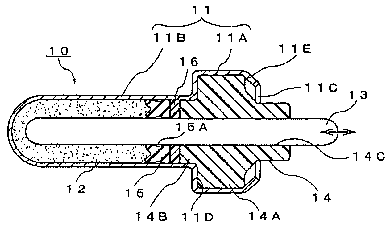
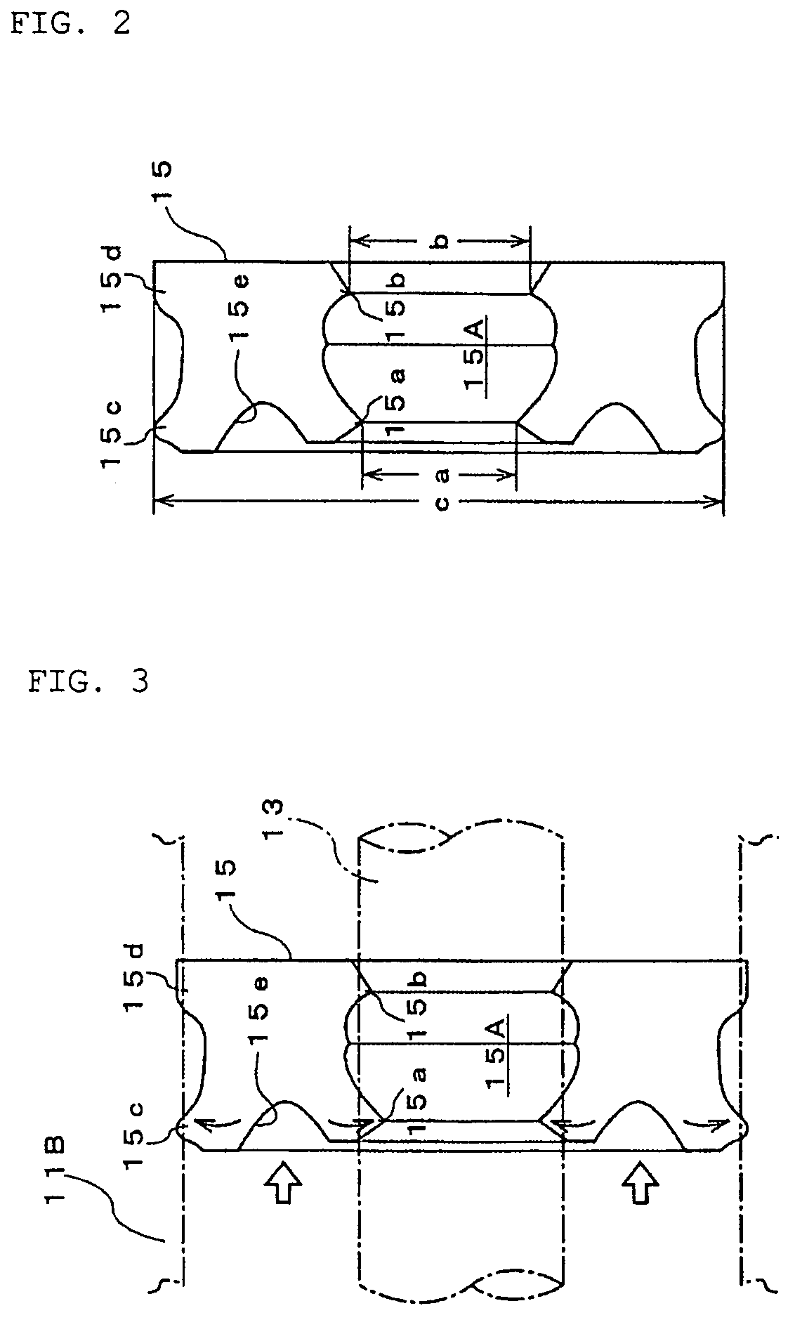
[0036]FIGS. 1 to 3 illustrate the thermal element in accordance with the present invention.

[0037]A thermal element denoted in those figures with the reference numeral 10 will be explained hereinbelow with reference to FIG. 1. Thus, the reference numeral 11 stands for a metal case constituting the thermal element body. Wax 12 serving as a thermally expandable body which thermally expands and shrinks under the effect of heat from the outside of the case 11 is sealed inside the case 11. The case 11 may be formed by press forming from any material capable of adequately transferring heat from the outside.

[0038]The reference numeral 13 stands for a piston disposed along the axial direction inside the case 11. Because the inward end of the piston 13 borders on the inside of the wax 12 and the outward end of the piston protrudes outwardly from one end of the case 11, the piston can move forward and backward along the axis, following the expansion and contraction of the wax. The operation of...

third embodiment

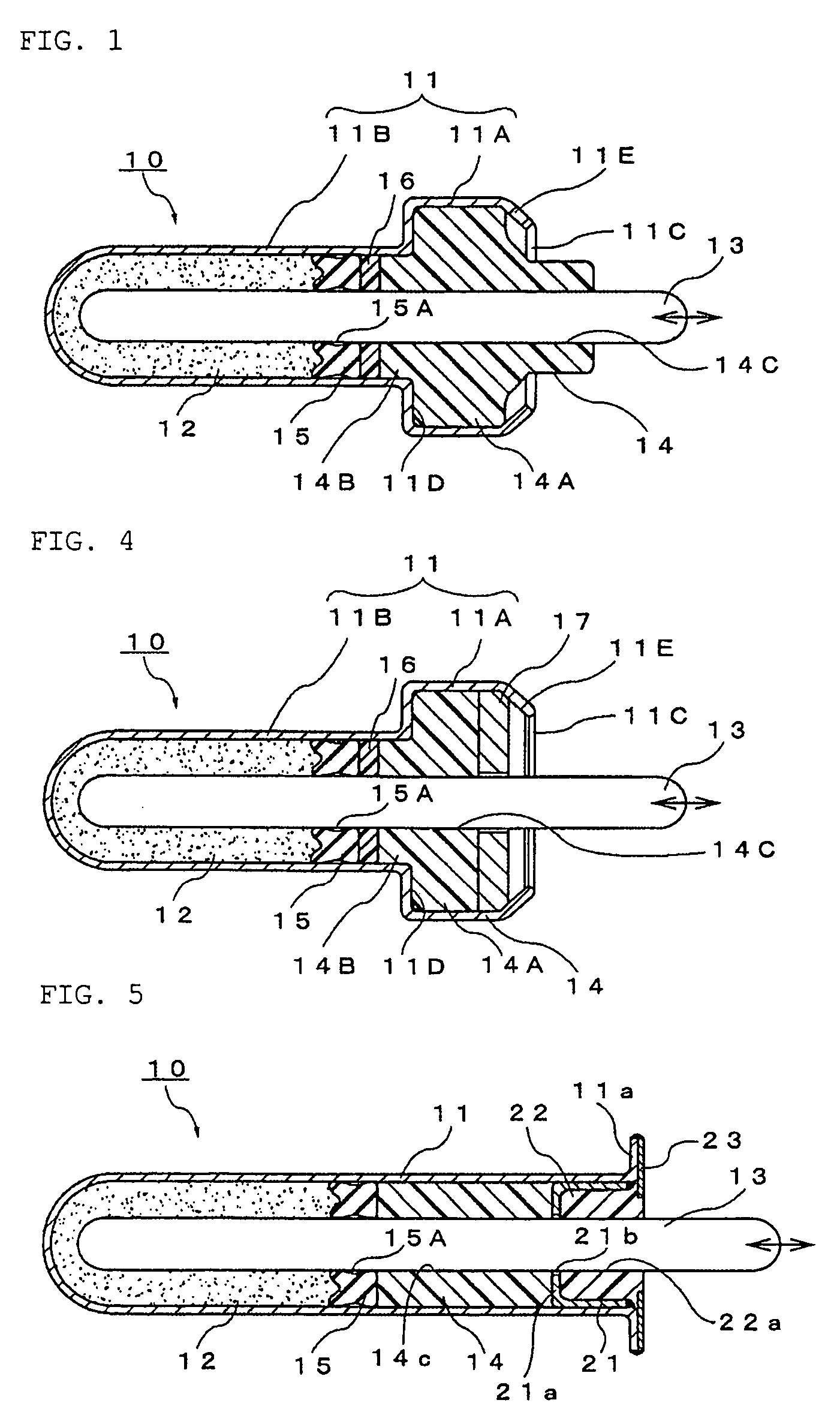
[0061]FIG. 5 illustrates the thermal element in accordance with the present invention.

[0062]In the figure, the thermal element denoted by the reference numeral 20 comprises a metal case 11 composed of a closed-end tubular hollow container having a substantially uniform diameter, and a wax 12 as a thermally expandable body that can be thermally expanded and contracted under the thermal effect from the outside of the case 11 is sealed in the closed-end portion of the case.

[0063]A piston 13 is disposed along the axial direction inside the case 11, the inward end of the piston borders on the inside of the wax 12 and the outward end thereof protrudes outwardly from the opening of the case 11, such a configuration allowing the piston to move forward and backward along the axial line, following the expansion or contraction of the wax 12. The operation of retracting the piston 13 into the case 11 is carried out by an impelling force, for example, of a return spring provided at the outside, ...


PUM

PropertyMeasurementUnit
temperatureaaaaaaaaaa
shapeaaaaaaaaaa

Abstract

A thermal element of a simple structure which can have a reduced cost because a minimum required number of structural components are used, excels in response and endurance and enables forward and backward movement of a piston with the prescribed stroke under the effect of volume changes following the expansion and contraction of a thermally expandable body.A thermal element 10 containing a thermally expandable body (wax 12) inside a case 11 comprises a piston 13 arranged inside the case along the axial line thereof. The inward end of the piston borders on the inside of the thermally expandable body and the outward end thereof protrudes outwardly from one end of the case, thereby enabling the piston to move forward and backward following the expansion and contraction of the thermally expandable body. The piston is slidably held with a guide member 14 disposed in a portion at one end inside the case. Furthermore, a sealing member 15 is disposed in a portion at the inward end of the guide member inside the case and seals the thermally expandable body at the other end inside the case.

Description

TECHNICAL FIELD[0001]The present invention relates to a thermal element suitable, for example for thermostats for actuating valves of fluid passages such as cooling water passages. More particularly, the present invention relates to a thermal element comprising a thermally expandable body which is expanded or contracted by temperature changes in a detection object such as cooling water, and a movable member (piston) which is moved by the thermally expandable body.BACKGROUND ART[0002]In cooling apparatuses of a cooling water type which are used to cool automobile engines, thermostats have been used as control valves for regulating the quantity of cooling water circulating in the radiator, thereby making it possible to control the temperature of cooling water introduced in the engine. A control valve in such thermostats is inserted into part of a cooling water passage constituting the cooling apparatus and the temperature of cooling water is controlled to the required level by closing...

Claims


Application Information

Patent Timeline
Patent Type & Authority Patents(United States)
IPC IPC(8): G05D23/12G05D23/02G01K5/44F01P7/16G12B1/04
CPCG05D23/021G01K5/44F25B21/00F25B21/02H10N10/00H10N15/00
Inventor INOUE, FUJIO
Owner NIPPON THERMOSTAT CO LTD
Why Eureka
Try Eureka