Golf club head

a golf club and head technology, applied in the field of golf club head, can solve the problems of carbon fiber plate and failure to provide colorful appearance, and achieve the effect of increasing the inertia moment of the golf club head and reducing weigh

Inactive Publication Date: 2007-02-13
FUSHENG IND CO LTD
View PDF12 Cites 145 Cited by
  • Summary
  • Abstract
  • Description
  • Claims
  • Application Information

AI Technical Summary

Benefits of technology

[0005]An object of the present invention is to provide a golf club head including a body having reduced weight in a crown thereof to allow adjustment of a center of gravity in a wider range and to increase the inertia moment of the golf club head.
[0006]Another object of the present invention is to provide a golf club head with improved visual effect and added value.SUMMARY OF THE INVENTION
[0007]In accordance with the present invention, a golf club head comprises a body and at least one transparent cover. The body includes a striking face for striking golf balls and a hosel for coupling with a shaft. The body includes a crown in which at least one opening is defined. A perimeter delimiting the opening includes a stepped portion. The transparent cover is securely mounted to the opening of the crown. The transparent cover is made of a transparent material having a specific gravity smaller than 1.5 g / cm3 for reducing a weight of the crown of the golf club head and for shifting a center of gravity of the golf club head downward and rearward.
[0014]The transparent cover may have a desired color. Further, the transparent cover may be convex or concave to provide a magnifying or reducing effect for the marking.

Problems solved by technology

Further, the color of the carbon fiber plates is black and thus fails to provide colorful appearances.

Method used


Image

  • Golf club head
  • Golf club head
  • Golf club head

Examples


first embodiment

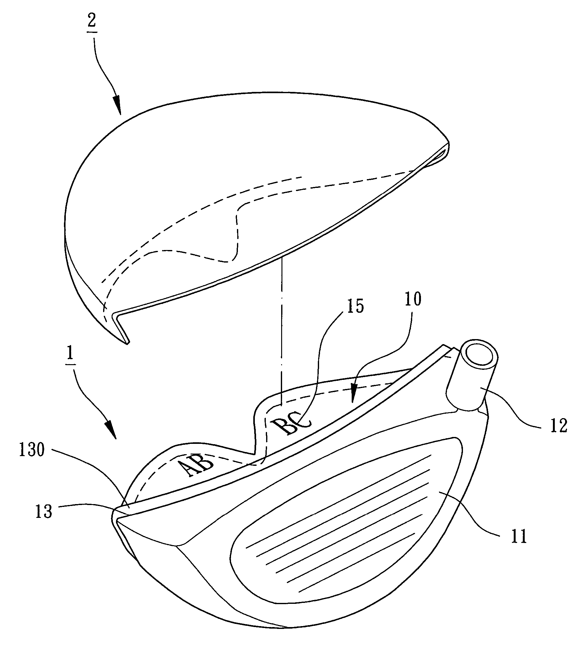
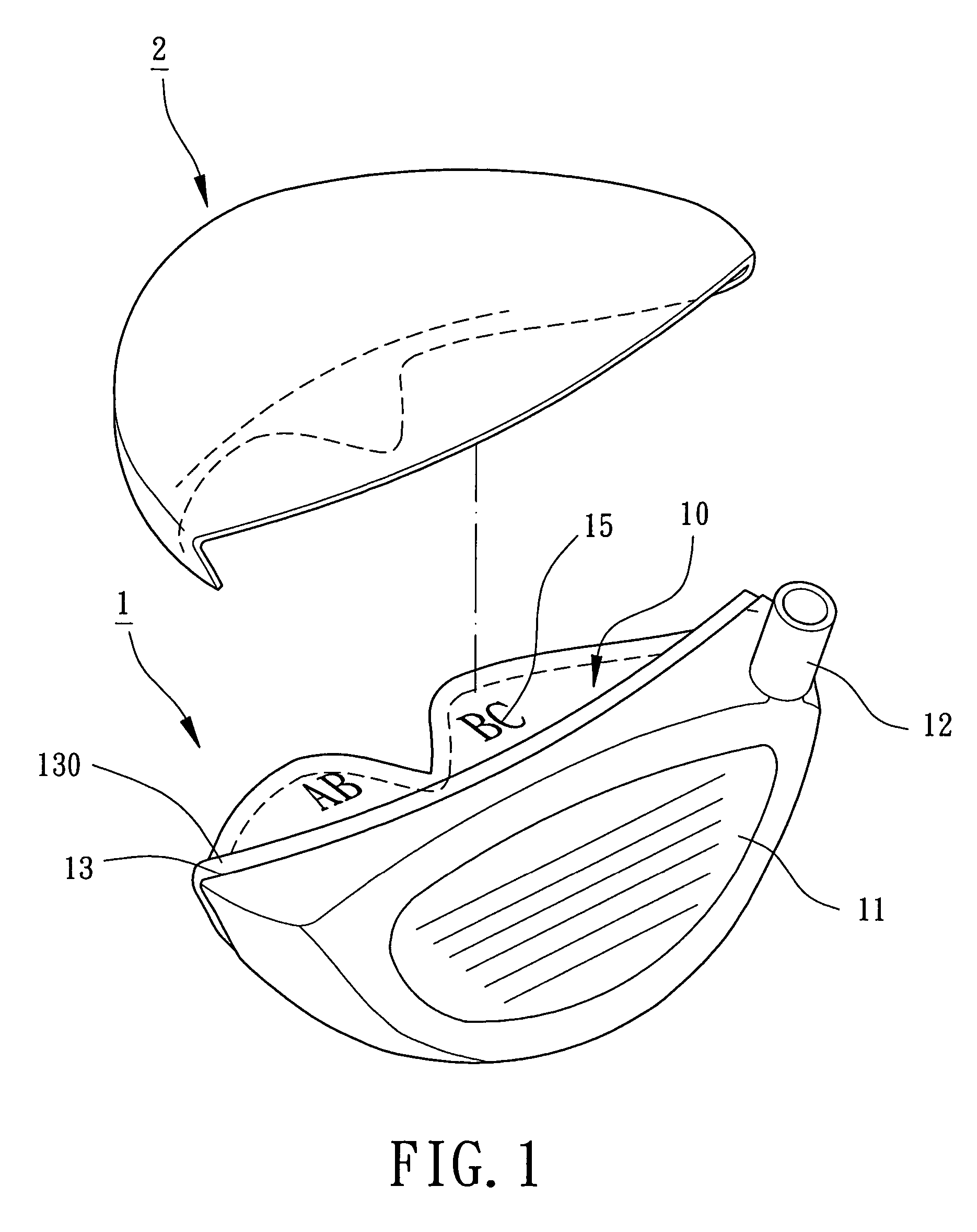
[0020]Referring to FIG. 1, a golf club head in accordance with the present invention comprises a body 1 and at least one transparent cover 2. The body 1 is made of metal or alloy having a relatively large specific gravity greater than 3.5 g / cm3, such as carbon steel, stainless steel, Fe—Mn—Al alloy, titanium alloy, etc. The body 1 can be obtained by means of integral formation or bonding several parts together. The body 1 includes a striking face 11, a hosel 12, and at least one opening 13. The striking face 11 is located on a front side of the body 1 for striking a golf ball. The hosel 12 is formed on a side of the body 1 for coupling with a shaft (not labeled). The opening 13 is defined in a crown of the body 1 and extends toward a toe, a heel, and a sole of the body 1. A perimeter delimiting the opening 13 includes a stepped portion 130 for coupling with the transparent cover 2.

[0021]The body 1 defines a compartment 10, with a marking area 15 being provided on an inner face of an...

second embodiment

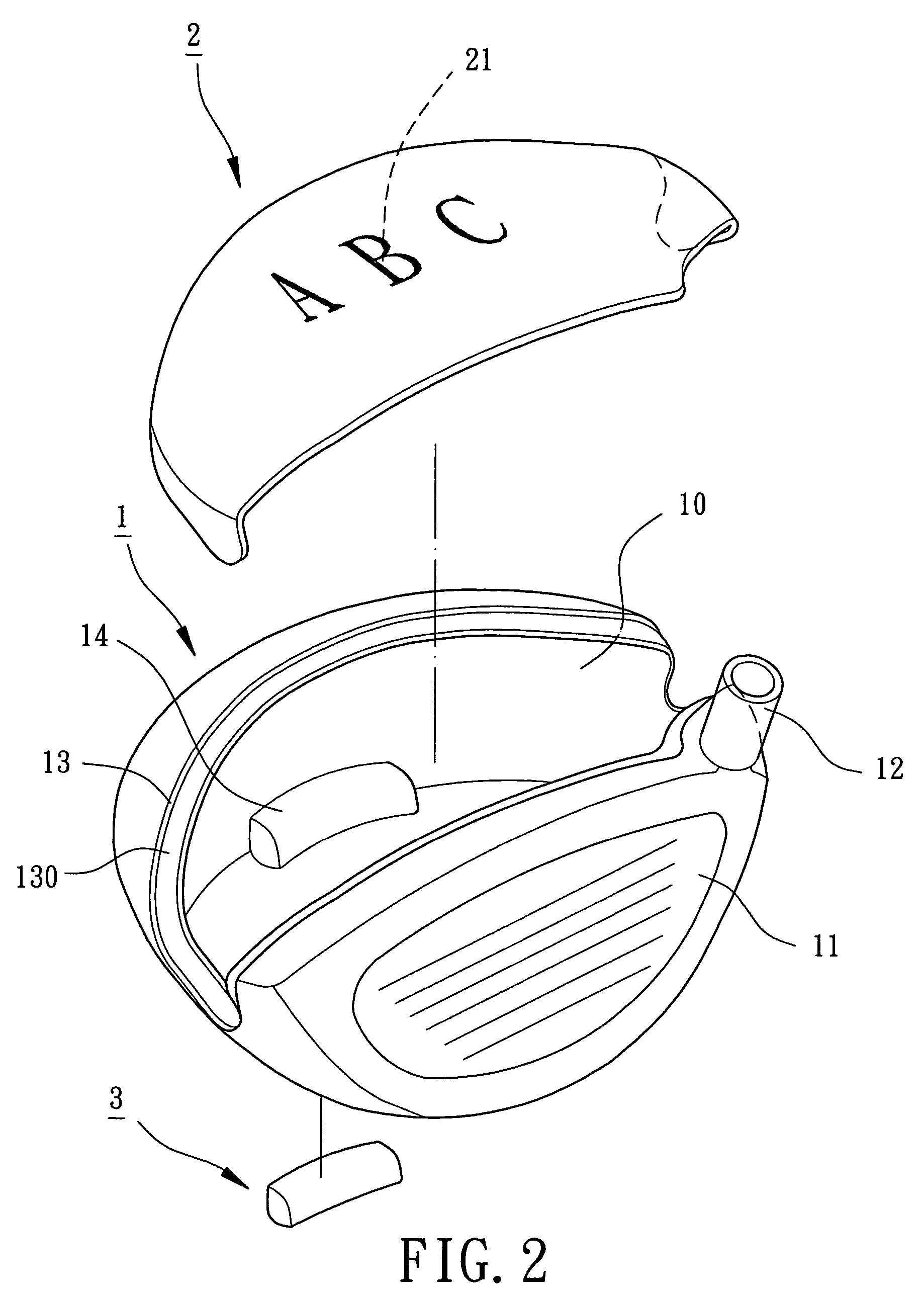
[0025]FIG. 2 illustrates the golf club head in accordance with the present invention, wherein the transparent cover 2 includes a marking area 21 in an inner face thereof. Further, the transparent cover 2 only extends toward the heel and the toe of the body 1. Letters, patterns, symbols, trademarks, etc can be provided in the marking area 15 by ink printing, laser engraving, sanding, sticking, or integral molding injection. Alternatively, a marking with reflection effect or laser refraction effect can be provided. Finishing to the inner wall delimiting the compartment 10 of the body 1 can be simplified while increasing the shift of the center of gravity of the golf club head and providing an aesthetically pleasing effect. Further, the body 1 includes a chamber 14 in a rear portion of the sole for receiving a weight member 3. The weight member 3 is made of metal or alloy with a large specific gravity, such as W—Fe—Ni alloy. The weight member 3 is preferably mounted in the chamber 14 b...


PUM


Abstract

A golf club head includes a body and at least one transparent cover. The body includes a striking face for striking golf balls and a hosel for coupling with a shaft. The body includes a crown in which at least one opening is defined. A perimeter delimiting the opening includes a stepped portion. The transparent cover is securely mounted to the opening of the crown. The transparent cover is made of a transparent material having a specific gravity smaller than 1.5 g / cm3 for reducing a weight of the crown of the golf club head and for shifting a center of gravity of the golf club head downward and rearward.

Description

BACKGROUND OF THE INVENTION[0001]1. Field of the Invention[0002]The present invention relates to a golf club head. In particular, the present invention relates to a golf club head with a lower and more rear center of gravity.[0003]2. Description of Related Art[0004]Japanese Patent Publication No. 2003-111874 discloses a golf club head comprising a body with an opening defined in a crown portion thereof. Two carbon fiber plates are respectively bonded to inner and outer sides of the opening. The carbon fiber plates have a specific gravity of about 1.8 g / cm3 and the body has a specific gravity of about 4.5 g / cm3. By means of using the carbon fiber plates to replace a portion of the crown of the body, the center of gravity of the body is shifted downward and rearward for increasing the inertia moment and for improving the striking effect. Shift of the center of gravity is limited, as the specific gravity of the carbon fiber plates could not be reduced. Further, the color of the carbon ...

Claims


Application Information

Patent Timeline
Patent Type & Authority Patents(United States)
IPC IPC(8): A63B53/04
CPCA63B53/0466A63B2053/0437Y10S273/14A63B53/0437
Inventor LO, LAI-FA
Owner FUSHENG IND CO LTD
Why Eureka
Try Eureka