
High frequency power source

a power source and high-frequency technology, applied in the field of high-frequency power sources, can solve the problems of reducing the ability of a pathologist to diagnose the sample, affecting the diagnosis of the sample, so as to facilitate the use of long electrodes, reduce the total power required, and increase the starting and sustaining voltag

Inactive Publication Date: 2007-02-13
SENORX
View PDF2 Cites 99 Cited by
  • Summary
  • Abstract
  • Description
  • Claims
  • Application Information

AI Technical Summary

Benefits of technology

[0010]An electrical power generator constructed in accordance with the invention is configured to produce electrical power at a frequency of about 1 MHz to about 14 MHz, preferably about 3 MHz to about 8 MHz. The electrical power generated preferably has an essentially sinusoidal waveform with a total harmonic distortion (THD) of less than 5%. The specified frequency and waveform help to minimize damage to adjacent tissue during electrosurgery. The power output has a high voltage level, for example, up to about 1,000 Vrms, and a high current level for example, between about 0.5 amps to 5 amps, particularly about 1 amp to 2 amps. The output of the electrosurgical power generator is connected to an electrosurgical tool configured to receive the voltage and current produced by the electrosurgical power generator and deliver the voltage and current to an electrosurgical site on a patient. There is preferably at least one ground pad in electrical contact with the patient to complete an electrical circuit for the system comprising the generator and the tool, thereby providing a controlled return path for the current from the electrosurgical site to the electrosurgical power generator.
[0012]The high frequency characteristics described above improve the electrosurgical power generator's ability to deliver consistent power over a range of electrical impedance loads caused by variations in tissue types.
[0014]Electrical power output with an essentially sinusoidal waveform in an electrosurgical procedure concentrates the electrical power into cutting tissue, thereby reducing the total power required during the electrosurgical procedure. Reduction in total power results in less heating, and thereby less damage to collateral tissue. Total power delivered during an electrosurgical procedure may also be reduced through duty factoring where the power is turned “on” and then “off” in rapid succession. When duty factoring the power output, the waveshape envelope may be, for example, a ramped, or trapezoidal rectangle, or a zero crossing switched rectangle.

Problems solved by technology

The variations in electrical impedance exhibited by these various tissue types can be problematic when attempting to perform electrosurgical cutting in such heterogeneous, or non-homogeneous, tissue.
If insufficient power is delivered by the power generator, the tissue cutting of the electrosurgical procedure will be inhibited.
If more power than necessary is delivered by the power generator there may excessive, and unnecessary, collateral tissue damage making it more difficult to perform a histology on a sample and thereby decreasing the ability of a pathologist to diagnosis the sample, as well as resulting in a more difficult recovery by the patient in addition to other sequela.
Generally, typical RF power generators experience difficulty in cutting through fatty non-homogeneous tissue because of the non-homogeneous tissue types that are typically encountered.
In addition, typical RF power generators are only effective with tools having small cutting surfaces.
In addition, because typical power generators are only effective for tools with small cutting surfaces, the types of tools available to a surgeon during electrosurgery are limited.
Electrosurgical tools, such as electrosurgical breast biopsy instruments, can present varying load requirements to an electrosurgical power generator than typical electrosurgical tools, due to the heterogeneous nature of the tissue they are used to cut or coagulate.

Method used


Image

  • High frequency power source
  • High frequency power source
  • High frequency power source

Examples


Embodiment Construction

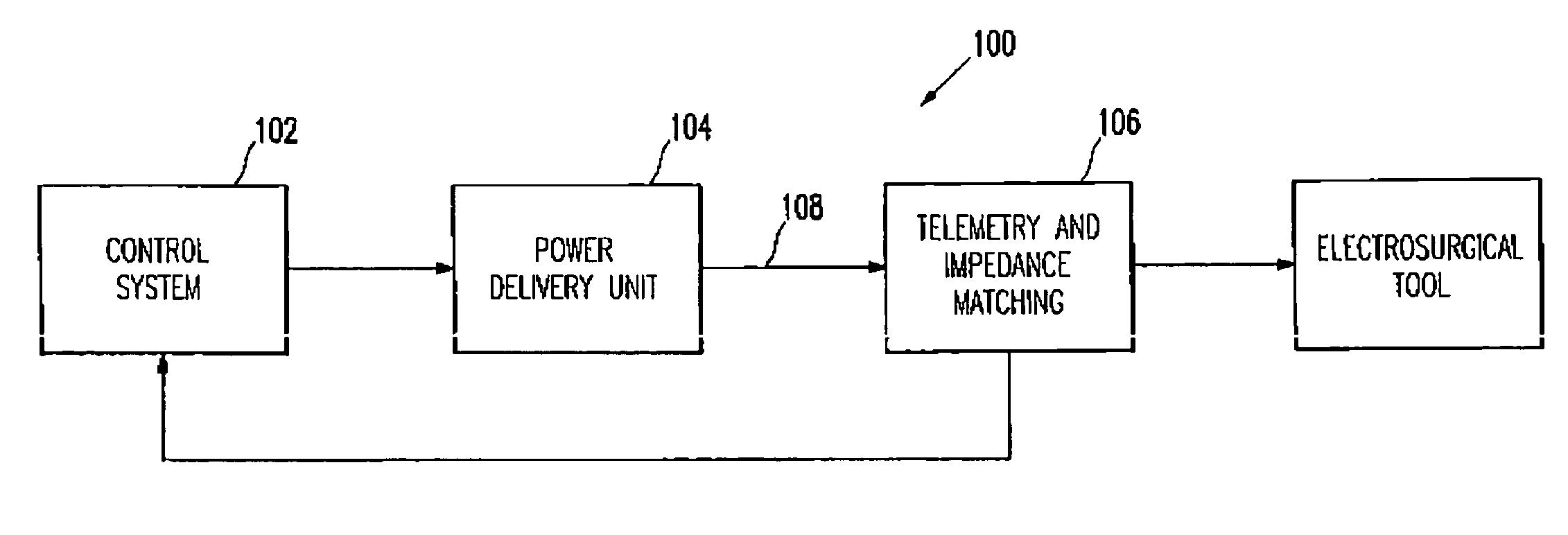
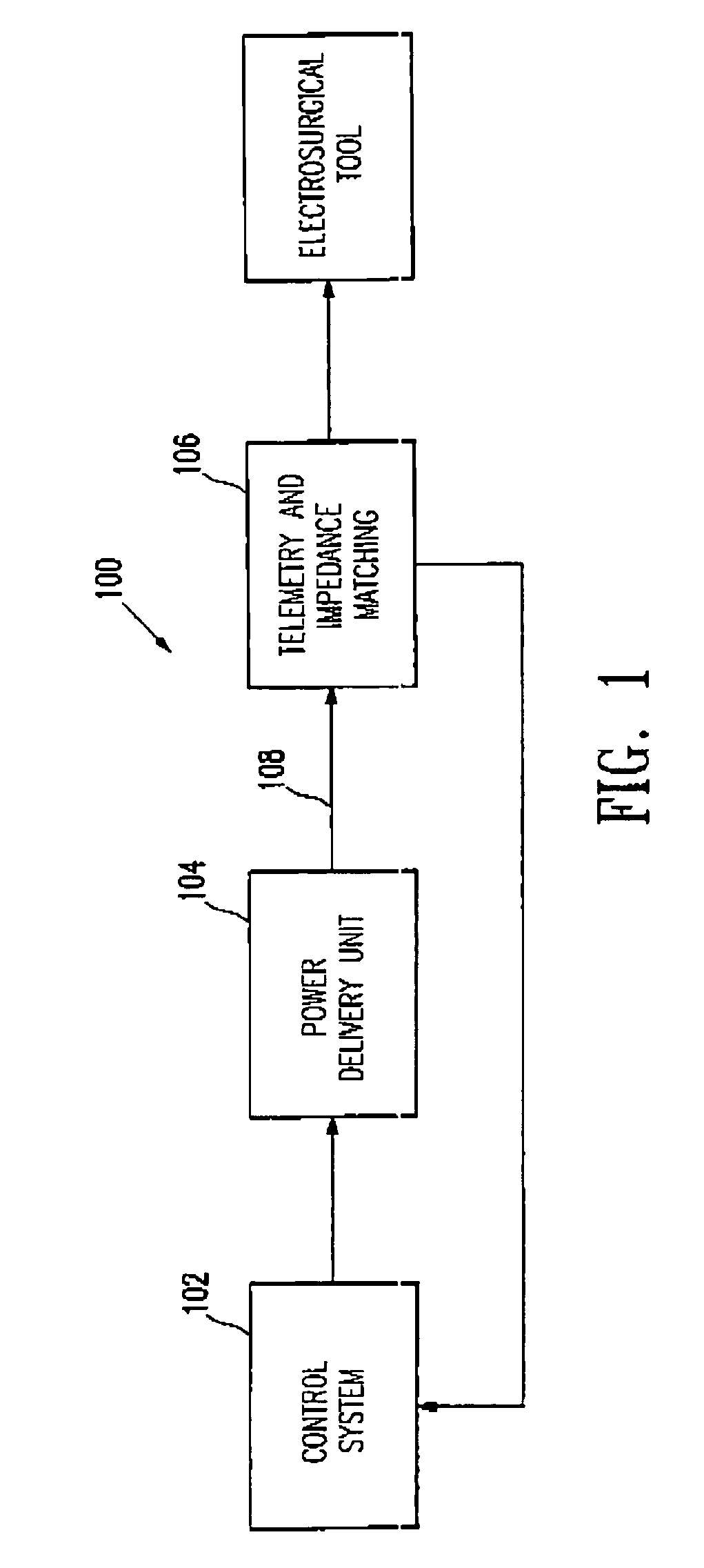
[0030]FIG. 1 is a block diagram illustrating a power delivery system 100 constructed in accordance with the invention for use in an electrosurgical procedure. The power delivery system 100 includes a control system 102. The control system generates a desired waveform for use in the electrosurgical procedure. The control system 102 outputs the desired waveform to a power delivery unit 104. The control system 102 condition the waveform, including, for example, amplitude control, gating and duty factor control. Gating and duty factor control are explained in more detail below. The power delivery unit 104 receives the desired waveform, amplifies and provides electrical capability, and outputs a power waveform. In one embodiment the power delivery unit may be a voltage controlled electrical power generating unit configured to produce a high frequency current having an essentially sinusoidal waveform having a total harmonic distortion (THD) of less than 5%.

[0031]The power waveform output ...


PUM


Abstract

A high frequency electrosurgical power generator configured to produce electrical power at a frequency of about 1 to about 14 MHz and preferably having an essentially sinusoidal waveform with a voltage level up to 1,000 Vrms, and a current level up to 5 Amps. The output of the high frequency electrosurgical power generator is connected to an electrosurgical tool configured to receive the voltage and current produced by the electrosurgical power generator and deliver the voltage and current to an electrosurgical site. The output of the electrosurgical generator preferably is an essentially sinusoid waveform with a frequency between about 3 MHz and about 8 MHz, up to about 700 volts rms, up to about 2 amps, with a total power of up to 1,000 watts.

Description

[0001]This application is a Divisional of Ser. No. 09 / 752,978 filed Dec. 28, 2000 now U.S. Pat. No. 6,620,157.BACKGROUND OF THE INVENTION[0002]Power generators used in electrosurgical procedures deliver electrical energy to an electrosurgical tool for operating on the tissue of a patient. An active electrode of the tool, connected to the power generator, concentrates the delivery of the electrical energy to a relatively small region of tissue of the patient. The electrical energy typically includes energy in the radio frequency (RF) band. The concentration of electrical energy facilitates cutting or coagulation of the tissue of the patient. During typical operation of a monopolar electrosurgical device, an alternating electrical current from the generator flows from an active electrode to a return electrode by passing through the tissue and bodily fluids of a patient.[0003]During an electrosurgical operation, different tissue types may be encountered, such as, for example, fat, conn...

Claims


Application Information

Patent Timeline
IPC IPC(8): A61B18/04A61B18/12
CPCA61B18/1206A61B18/18A61B2018/00702A61B2018/00827A61B2018/1213A61B2018/00601A61B2018/00666A61B2018/00892A61B2018/00726A61B18/1233A61B18/16A61B2018/00607A61B2018/00875A61B2018/00898A61B2018/0094A61B2018/1266A61B2018/1286A61B2018/162
Inventor DABNEY, JAMES HUNTINGTONQUICK, RICHARD L.SAWICZ, CONRADLUBOCK, PAULKUSSMAN, DAN
Owner SENORX
Learn More