Ejector to reduce permeate backpressure of air separation module

a technology of air separation module and air bleed air, which is applied in the direction of separation process, membrane, dispersed particle separation, etc., can solve the problems of engine efficiency reduction, high-pressure bleed air use, etc., to improve oxygen removal capacity, reduce engine efficiency, and increase the momentum of exhaust flow

Active Publication Date: 2007-02-13
HAMILTON SUNDSTRAND CORP
View PDF4 Cites 24 Cited by
  • Summary
  • Abstract
  • Description
  • Claims
  • Application Information

AI Technical Summary

Benefits of technology

[0011]An ejector releases high-pressure air adjacent the exhaust opening of the air separation module to increase the momentum of the exhaust flow, and thereby the pressure differential across the air separation module. Exhausting high-pressure air through the ejector adjacent the exhaust maintains the desired pressure differential that provides the desired magnitude of oxygen diffusion from the high-pressure bleed air.
[0012]The use of high-pressure bleed air reduces engine efficiency. Therefore, a shut off valve discontinues the flow of high-pressure air to the ejector when not required to maintain the desired pressure differential. During high speed cruising at altitude, the pressure differential provided by the pressure level of the ram airflow from the environmental control system is sufficient to provide the desired oxygen diffusion, and therefore high-pressure bleed air from the ejector is not required.
[0013]Accordingly, the air separation system of this invention provides improved oxygen removal capacity while maintaining desired engine efficiencies.

Problems solved by technology

The use of high-pressure bleed air reduces engine efficiency.

Method used


Image

  • Ejector to reduce permeate backpressure of air separation module
  • Ejector to reduce permeate backpressure of air separation module

Examples


Embodiment Construction

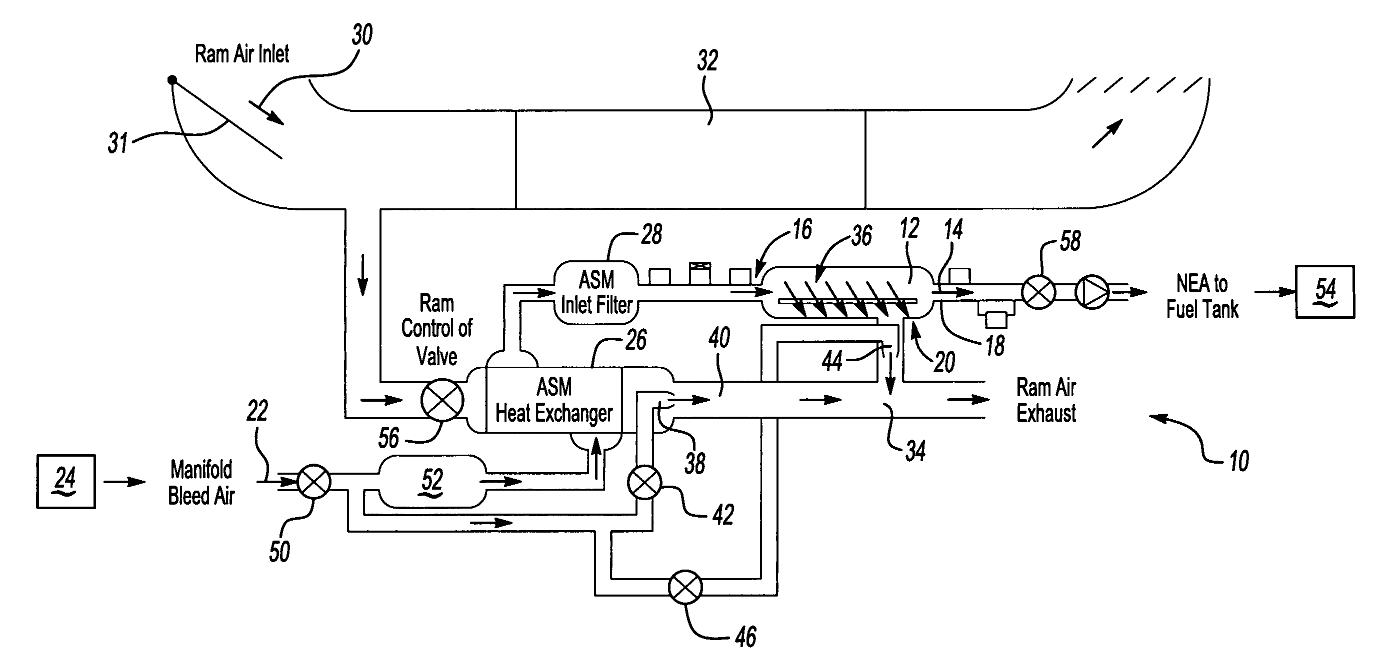
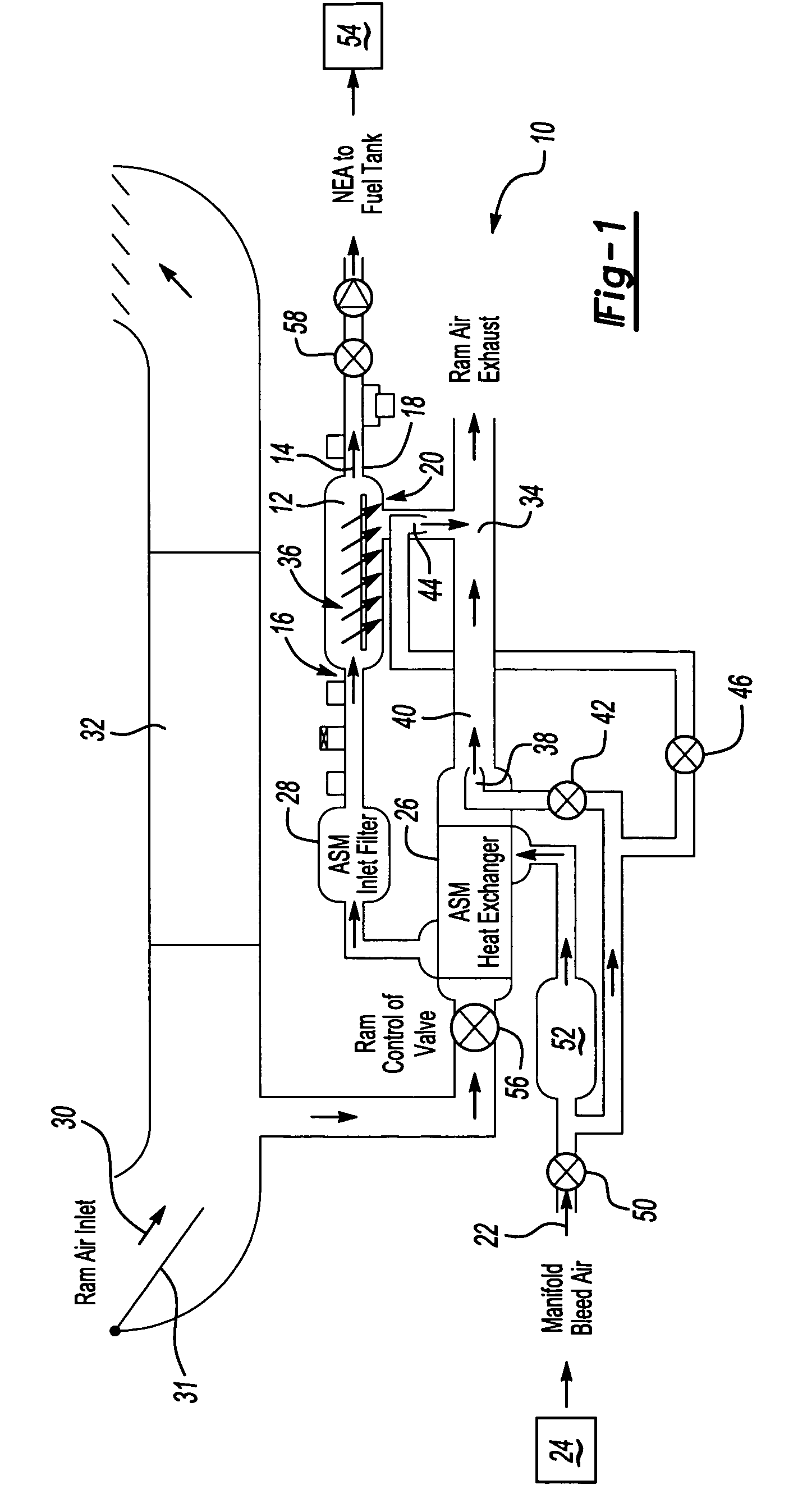
[0016]Referring to FIG. 1, an air separation system 10 includes an air separation module 12 for removing oxygen from an air stream 14. The air separation module 12 includes an inlet 16, outlet 18 and an exhaust 20. Bleed air 22 from an engine 24 or from a motor-driven compressor is cooled within a heat exchanger 26 and flowed through a filter 28 before entering the inlet 16 of the air separation module 12.

[0017]Ram air 30 from an environmental control system 32 is flowed through the heat exchanger 26 and is in thermal communication with bleed air 22 from the engine 24. Ram air 30 exiting the heat exchanger 28 flows through an exhaust passage 34 and exhausted overboard.

[0018]The exhaust 20 of the air separation module 12 is in communication with the exhaust passage 34 and creates a pressure differential between the air separation module inlet 16 and the exhaust 20. The pressure differential drives diffusion of oxygen 36 from the bleed air 22. The magnitude of pressure differential go...


PUM

PropertyMeasurementUnit
pressureaaaaaaaaaa
temperatureaaaaaaaaaa
permeableaaaaaaaaaa

Abstract

An air separation system includes an ejector for controlling a pressure differential across an air separation module and a valve for controlling air flow through the ejector such that airflow through the ejector is discontinued when not required to maintain the desired pressure differential across the air separation module.

Description

BACKGROUND OF THE INVENTION[0001]This invention generally relates to an air separation module and specifically to an air separation module for a fuel inerting system.[0002]A fuel tank for an aircraft contains fuel vapors along with liquid fuel. Oxygen rich air within the fuel tank combined with the fuel vapors can cause an undesirable reaction. Fuel tank inerting systems are known that replace the oxygen rich air with an inert gas to substantially reduce the oxygen content within the fuel tank and thereby substantially reduce the possibility of fuel vapor ignition.[0003]Typically, an onboard fuel tank inerting system replaces oxygen rich air with nitrogen enriched (oxygen depleted) air that renders the tank inert. Removing a significant amount of oxygen from an air stream creates the nitrogen-enriched air. The air stream is typically obtained from a component of a main engine such as an intake manifold or compressor of a gas turbine engine. An air separation module is provided for r...

Claims


Application Information

Patent Timeline
Patent Type & Authority Patents(United States)
IPC IPC(8): B01D53/22B64D37/32
CPCB01D53/22B01D63/00B01D63/02B64D37/32Y02T50/44B01D2313/38B64D2013/0677B01D2313/18Y02T50/40B01D2313/221
Inventor SCHWALM, GREGORY
Owner HAMILTON SUNDSTRAND CORP
Why Eureka
Try Eureka