Natural gas deacidizing and dehydration method

Inactive Publication Date: 2007-02-13
INST FR DU PETROLE
View PDF6 Cites 21 Cited by
  • Summary
  • Abstract
  • Description
  • Claims
  • Application Information

AI Technical Summary

Benefits of technology

[0031]The method according to the present invention has the advantage of carrying out deacidizing and dehydration of a natural gas with a single solvent containing amines circul

Problems solved by technology

The fact that the amines are in aqueous solution does not allow dehydration of the gas to be treated and has the drawback of moistening a gas which would be intrinsically dry or which would have already

Method used


Image

  • Natural gas deacidizing and dehydration method
  • Natural gas deacidizing and dehydration method

Examples


Example

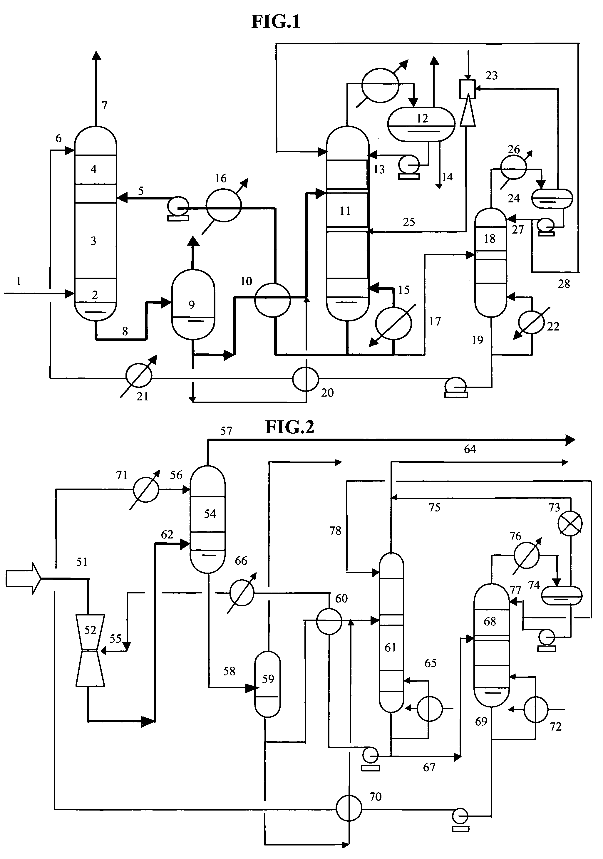
[0035]In FIG. 1, the natural gas containing water and acid compounds such as H2S and CO2 flows through line 1 into absorption column 2. Column 2 comprises two absorption zones 3 and 4. Zones 3 and 4 can be superposed in a column. Absorption zones 3 and 4 can also be arranged in two different columns. First absorption zone 3 allows extraction of the acid compounds (H2S and possibly CO2), second absorption zone 4 allows dehydration and possibly ultimate deacidizing of the gas. The gas flowing in through line 1 is brought into countercurrent contact in zone 3 with a regenerated solvent introduced through line 5. The solvent consists of an aqueous amine solution allowing absorption of the acid compounds (H2S and possibly CO2) contained in the natural gas. A deacidized water-saturated gas is obtained at the top of zone 3 and fed to zone .4. The solvent containing acid compounds (H2S and possibly CO2) collected at the bottom of zone 3 is discharged through line 8. The gas fed into zone 4 ...


PUM


Abstract

The natural gas is deacidized by contacting in zone 3 with a solvent containing amine in aqueous solution. The gas is then dehydrated by contacting in zone 4 with a solvent very rich in amine. After the contacting operations, the solvent containing H2S. and water is expanded in drum 9, then regenerated in column 11. Part of the regenerated solvent is sent to zone 3. Another part of the regenerated solvent is vacuum distilled in column 18 so as to produce an amine-rich solvent that is sent to zone 4.

Description

FIELD OF THE INVENTION[0001]The present invention relates to the sphere of treatment of a natural gas from a petroleum production well. It provides a natural gas deacidizing and dehydration method.[0002]During production of a natural gas intended to be marketed, the necessity of reducing the hydrogen sulfide content (H2S) to some parts per million is essential for safety reasons. Since carbon dioxide (CO2) is not a poison, it can be allowed in proportions of some volume percents. The CO2 content is only limited by considerations of heat capacity of the gas and of pressure drop in the pipelines. Natural gas dehydration is necessary to prevent pipeline corrosion and / or to prevent formation of ice and hydrate plugs.BACKGROUND OF THE INVENTION[0003]Methods of the prior art provide extraction of the acid gases. (H2S and CO2) by means of a treatment using a solvent containing amines, for example methyldiethanolamine (MDEA), which has a very high affinity with H2S.[0004]The amines used by ...

Claims


Application Information

Patent Timeline
IPC IPC(8): B01D53/14B01D53/26C10L3/10
CPCB01D53/1425B01D53/1456C10L3/102C10L3/10B01D53/263
Inventor MINKKINEN, ARIROJEY, ALEXANDRELECOMTE, FABRICE
Owner INST FR DU PETROLE
Why Eureka
Try Eureka