Fuel cell system

a fuel cell and system technology, applied in electrochemical generators, process and machine control, instruments, etc., can solve the problems of fuel cell arrangement, soot formation, and inability to meet the needs of supply fuels

Inactive Publication Date: 2007-02-13
EHNERDEJ GMBKH
View PDF7 Cites 3 Cited by
  • Summary
  • Abstract
  • Description
  • Claims
  • Application Information

AI Technical Summary

Benefits of technology

[0011]A primary object of the present invention is to provide a fuel cell system which enables reliable operation in the starting phase and recirculation of the anode exhaust gas, where the anode exhaust gas can be supplied either to the reformer or the fuel cell arrangement.

Problems solved by technology

One known problem in partial oxidation is soot formation.
Both when the fuel is being supplied to a fuel cell arrangement and also when a fuel is being supplied to a reformer there is the problem during the starting phase of the system.
That is, the supplied fuels are not yet suitable or the reformer and the fuel cell arrangement have not yet reached the necessary operating temperature to enable proper operation.
While this arrangement does solve the problem of the starting phase, this system is comparatively expensive.
Additionally, both the valves and the injectors have a complex structure.
Moreover, there additional piping is necessary which makes the system structure more complicated and leads to pressure losses and higher costs.

Method used


Image

  • Fuel cell system
  • Fuel cell system
  • Fuel cell system

Examples


Embodiment Construction

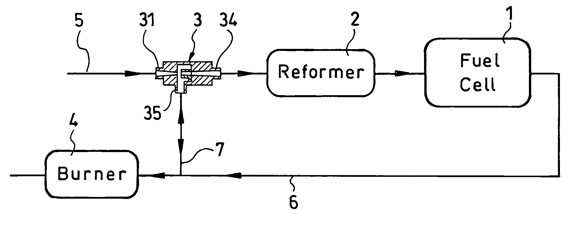
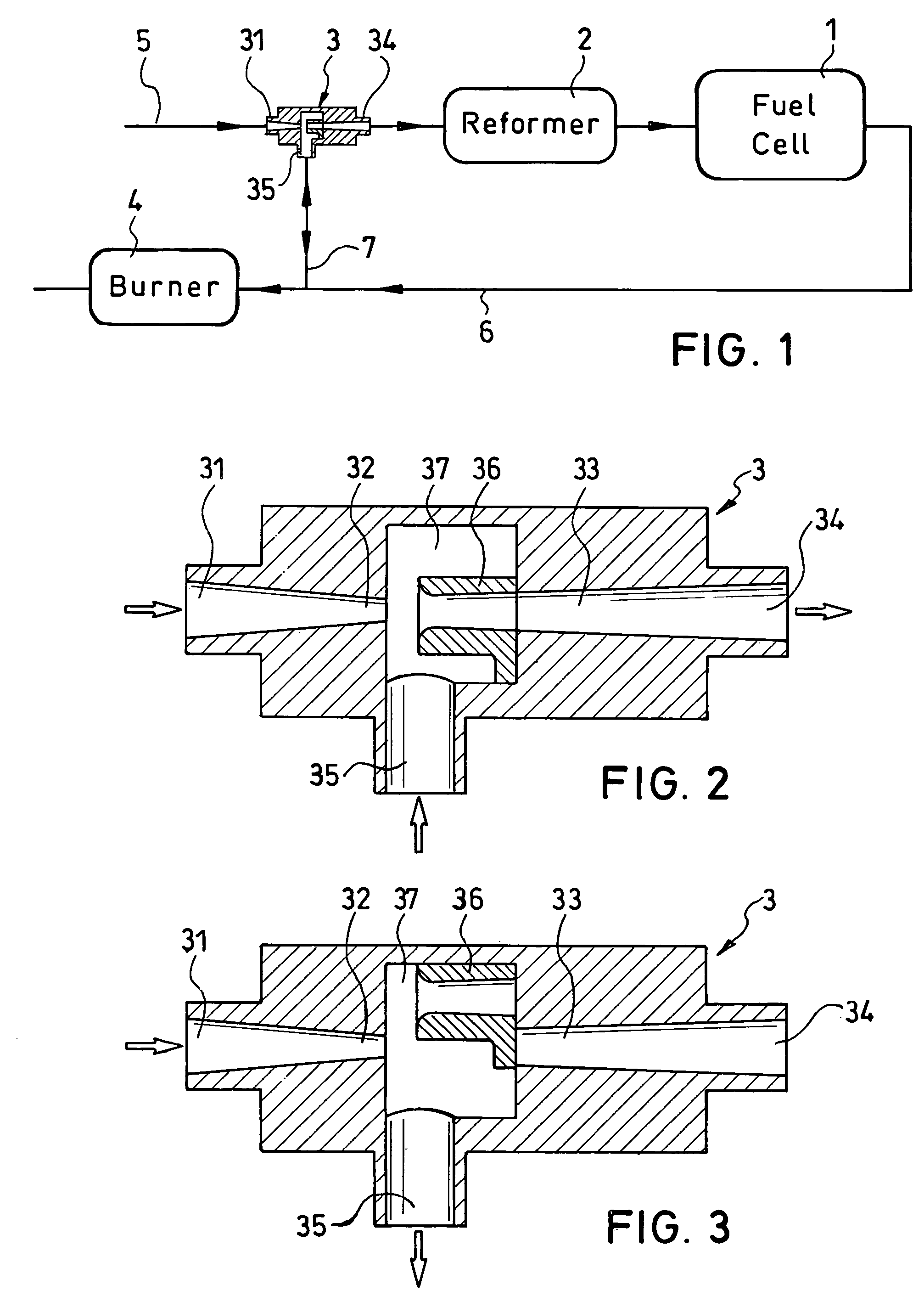
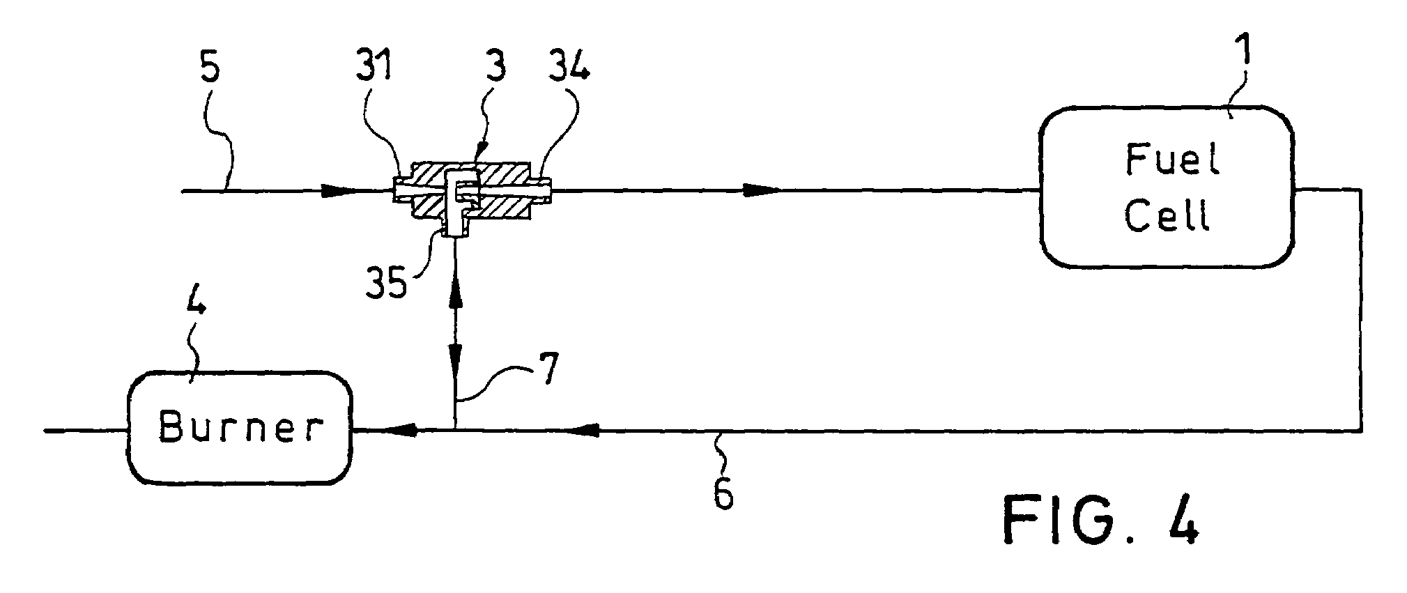
[0021]In the fuel cell system shown in FIG. 1, a liquid or gaseous fuel, e.g., gasoline, is used to produce a hydrogen-containing gas by a reforming reaction. A reformer 2 is provided, and the reformate from the reformer 2 is supplied to the fuel cell arrangement 1. The fuel cell arrangement 1 has connections (not shown) by which the electrical current produced can be directly tapped. In the supply of the fuel to the reformer 2, there is an injector 3 which accelerates the fuel supplied via a line 5 and thus reduces the static pressure. This negative pressure makes enable the intake the anode exhaust gas via the intake opening 35 and the line 7. In the diffuser 33, the pressure rises again. The injector 3 in this embodiment can be supplied, via the fuel line 5, not only with fuel, but also with a fuel-air mixture which is to be delivered to the reformer 2.

[0022]This mode of operation is steady-state when all components of the fuel cell system are at the operating temperature.

[0023]I...


PUM

PropertyMeasurementUnit
temperaturesaaaaaaaaaa
entry areaaaaaaaaaaa
areaaaaaaaaaaa

Abstract

A fuel cell system in which fuel is supplied to a fuel cell arrangement and/or a reformer by an injector, where the anode exhaust gas of the fuel cell arrangement is recirculated to the injector. The fuel cell arrangement is connected to an intake opening of the injector which also has an inlet opening, a following nozzle, a following diffuser with an outlet opening and an intake opening for feed of the anode exhaust gas of the fuel cell arrangement. A chamber is formed between the nozzle and the entry area of the diffuser, and a slide is positioned within the chamber to move from a first slide position permiting the passage of the fuel from the nozzle to the outlet opening and a second slide position where the passage of fuel is prevented.

Description

BACKGROUND OF THE INVENTION[0001]1. Field of the Invention[0002]The invention relates to a fuel cell system including a fuel cell arrangement and an injector for returning the exhaust gas to the fuel cell arrangement. The injector includes an inlet opening, a following nozzle, a following diffuser with an outlet opening and an intake opening for feed of the anode exhaust gas of the fuel cell arrangement to a chamber which has been formed in the area of the nozzle and the entry area of the diffuser. Furthermore, the invention is directed to a fuel cell system with a fuel cell arrangement, a reformer for reforming a liquid or gaseous fuel into a hydrogen-containing gas and an injector for return of the exhaust gas to the reformer, the injector having an inlet opening, a following nozzle, a following diffuser with an outlet opening and an intake opening for feed of the anode exhaust gas of the fuel cell arrangement to a chamber which has been formed in the area of the nozzle and of the...

Claims


Application Information

Patent Timeline
Patent Type & Authority Patents(United States)
IPC IPC(8): H01M8/04G05D11/02H01M8/02H01M8/06
CPCH01M8/04097H01M8/04022Y02E60/50H01M8/0612Y10T137/2572
Inventor BOLTZE, MATTHIAS
Owner EHNERDEJ GMBKH
Why Eureka
Try Eureka