
Method and apparatus for outputting constant voltage

a constant voltage and output voltage technology, applied in the direction of instant pulse delivery arrangement, instrument, orbital function generator, etc., can solve the problems of deterioration in output voltage vout accuracy and light weight of lithium ion batteries

Active Publication Date: 2007-02-13
NISSHINBO MICRO DEVICES INC
View PDF5 Cites 29 Cited by
  • Summary
  • Abstract
  • Description
  • Claims
  • Application Information

AI Technical Summary

Benefits of technology

"The patent describes a novel constant voltage outputting apparatus that includes a differential amplifier circuit, an amplifier circuit, a current adjustment device, a stabilization circuit, and an output voltage control device. The differential amplifier circuit receives an input voltage, a reference voltage, and a feedback voltage and performs a differential amplifying operation to output a differential amplified voltage. The amplifier circuit amplifies the differential amplified voltage. The current adjustment device adjusts the current characteristic of the amplifier circuit. The stabilization circuit stabilizes the state of the current adjustment device. The output voltage control device controls the output voltage to an external load based on the input voltage. The patent also describes a method for constant voltage outputting. The technical effects of the invention include improved accuracy and stability of voltage output, improved control of output voltage, and improved stability of the current adjustment device."

Problems solved by technology

Further, the lithium ion battery is light in weight.
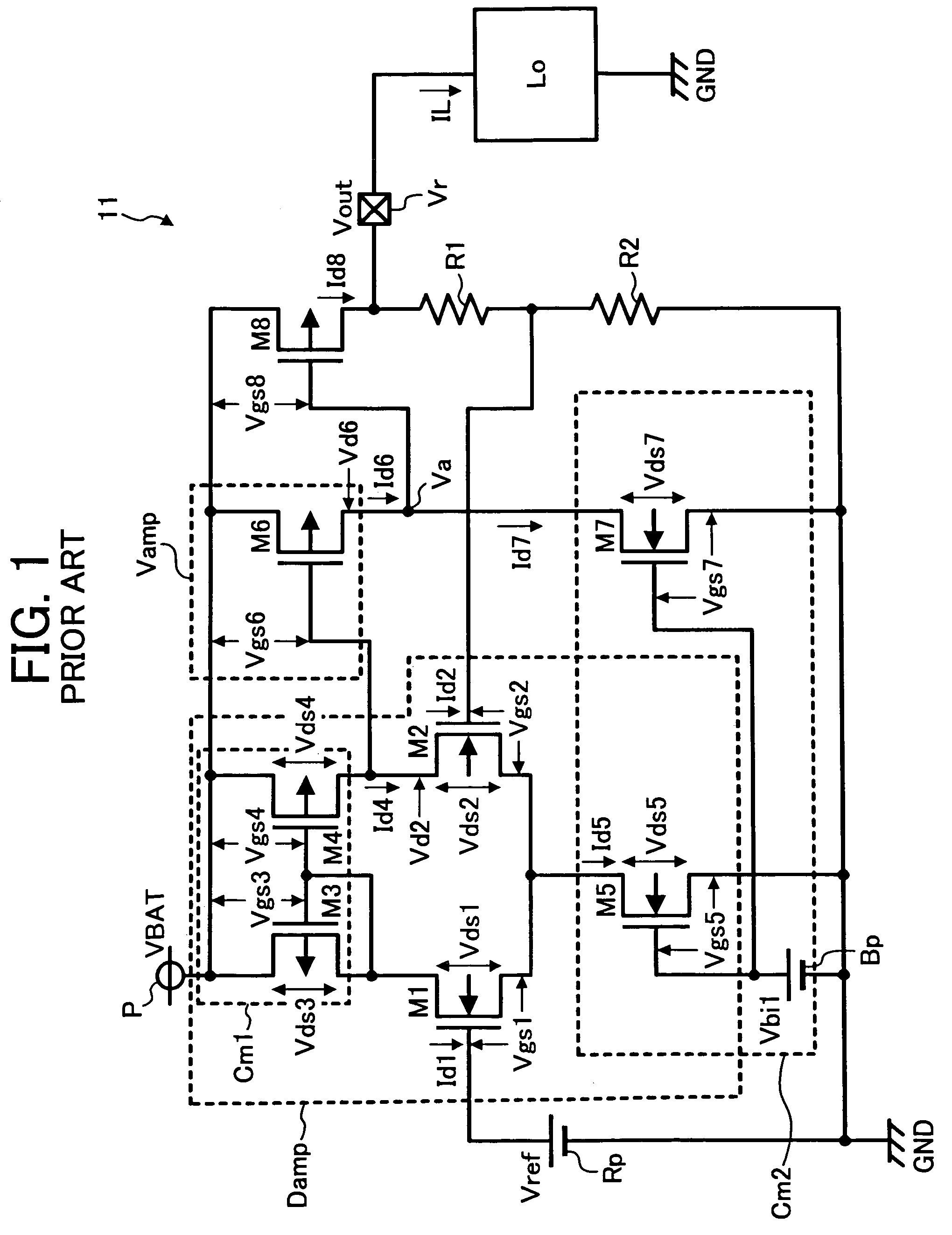
However, the above background constant voltage circuit 11 has a problem that, within the differential amplifier circuit Damp, a balance is lost between the drain current Id1 of the differential input transistor M1 and the drain current Id2 of the differential input transistor M2 and thus there arises an input offset voltage, which is a difference in voltage between the gate (i.e., an input terminal) of the differential input transistor M1 and the gate (i.e., an input terminal) of the differential input transistor M2, causing deterioration in accuracy of the output voltage Vout.

Method used


Image

  • Method and apparatus for outputting constant voltage
  • Method and apparatus for outputting constant voltage
  • Method and apparatus for outputting constant voltage

Examples


Embodiment Construction

[0053]In describing preferred embodiments illustrated in the drawings, specific terminology is employed for the purpose of clarity. However, the disclosure of this patent specification is not intended to be limited to the specific terminology so used and it is to be understood that substitutions for each specific element can include any technical equivalents that operate in a similar manner.

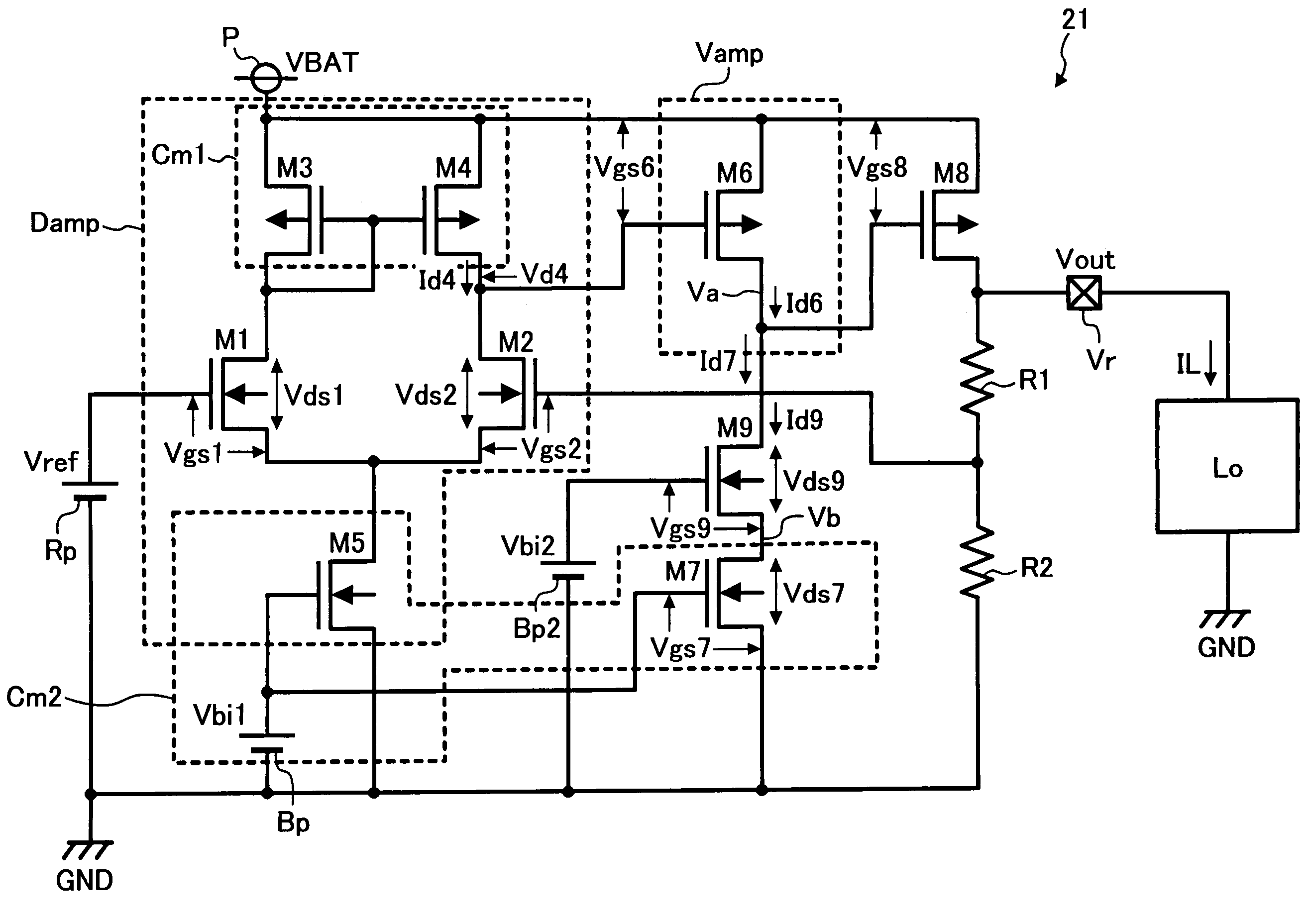
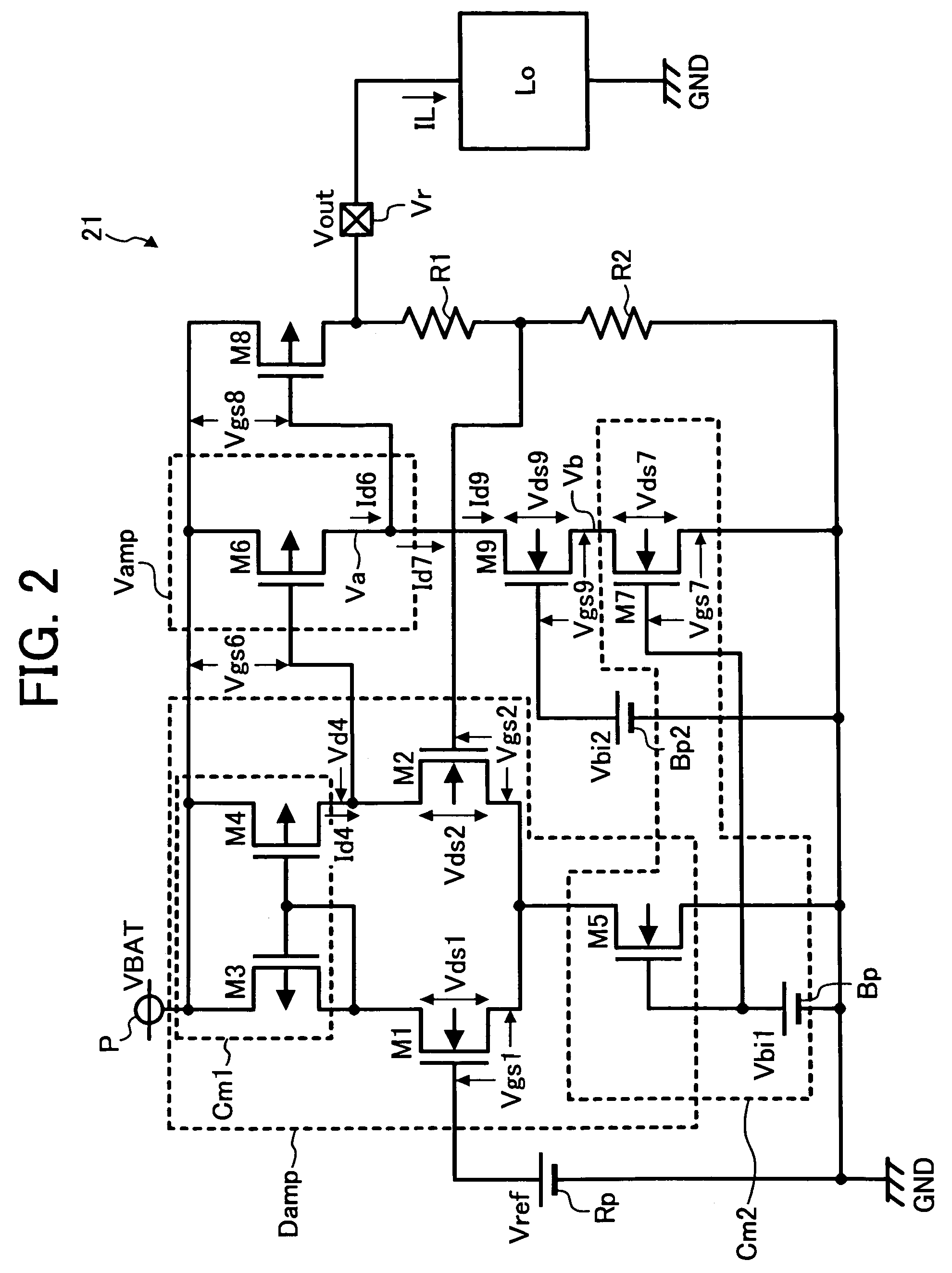
[0054]Referring now to the drawings, wherein like reference numerals designate identical or corresponding parts throughout the several views, FIG. 2 illustrates a configuration of a constant voltage circuit 21 according to an exemplary embodiment. Description is omitted for components of the constant voltage circuit 21 which are also components of the background constant voltage circuit shown in FIG. 1.

[0055]As illustrated in FIG. 2, the present constant voltage circuit 21 includes, as a stabilization circuit, a bias voltage source Bp2 and a stabilization transistor M9. The stabilization transist...


PUM


Abstract

A constant voltage outputting apparatus includes a differential amplifier circuit, an amplifier circuit, a current adjustment device and a stabilization circuit. The differential amplifier circuit performs a differential amplifying operation and outputs a differential amplified voltage. The amplifier circuit amplifies the differential amplified voltage output from the differential amplifier circuit. The current adjustment device adjusts a current characteristic of the amplifier circuit. The stabilization circuit stabilizes a state of the current adjustment device. A constant voltage outputting method is also described.

Description

BACKGROUND[0001]1. Field[0002]This patent specification relates to a method and apparatus for outputting a constant voltage to a load by using a differential amplifier circuit.[0003]2. Discussion of the Background[0004]In recent years, a lithium ion battery has been widely used as a power source for mobile devices. The operating voltage of the lithium ion battery is about 3.7 V, which is approximately three times of an operating voltage of a Ni—Cd battery or a nickel hydride battery. Therefore, the lithium ion battery can reduce the number of batteries used in a mobile device. Further, the lithium ion battery is light in weight. Accordingly, the lithium ion battery contributes to reduction in size and weight of the mobile device. When the lithium ion battery is used in the mobile device, however, an initial voltage of the lithium ion battery immediately after charging is about 4.3 V, but a final voltage of the battery after discharging is reduced to about 3.2 V. Therefore, the volta...

Claims


Application Information

Patent Timeline
Patent Type & Authority Patents(United States)
IPC IPC(8): G06G7/12G05F1/10G05F1/56G05F1/575H03K5/153
CPCG05F1/575
Inventor NODA, IPPEIITOH, KOHZOH
Owner NISSHINBO MICRO DEVICES INC
Learn More