Compact objective optical system and examination apparatus

a technology of objective optical system and objective lens, which is applied in the field of compact objective optical system, can solve the problems of inability to carry out long-term examination, large incision in living organism, and high invasiveness, and achieves wide observation range, long length, and overall length increase

Active Publication Date: 2007-02-13
EVIDENT CORP
View PDF3 Cites 20 Cited by
  • Summary
  • Abstract
  • Description
  • Claims
  • Application Information

AI Technical Summary

Benefits of technology

[0010]The present invention has been conceived in light of the circumstances described above, and an object thereof is to realize an objective optical system, as well as an examination apparatus using the same, in which the outer diameter is reduced, the overall length is increased, and chromatic aberrations are well-corrected and which is suitable for in-vivo examination with a sufficiently long length and a wide observation range.

Problems solved by technology

Making a large incision in a living organism, however, is highly invasive, and therefore long-term examination is impossible.
However, because the overall optical-system length in the objective optical system disclosed in Japanese Unexamined Patent Application Publication No. 2004-313772 is small, it is difficult to insert the objective lens to the position of an internal organ that is deep inside the living organism.
Also, this objective optical system suffers from the problem that the observation range is too small to examine changes at the tissue level.
Furthermore, the objective optical system disclosed in United States Patent Application No. 2004 / 0051957A1 does not sufficiently correct chromatic aberrations.
Therefore, when carrying out white-light observation or fluorescence observation with this objective optical system, the wavelengths of excitation light and fluorescence produced in the specimen differ, which results in the problem of low resolution.
This is a problem particularly when carrying out fluorescence observation using a confocal optical system, because the brightness of the fluorescence detected is low if the chromatic aberrations are not corrected.

Method used


Image

  • Compact objective optical system and examination apparatus
  • Compact objective optical system and examination apparatus
  • Compact objective optical system and examination apparatus

Examples


first example

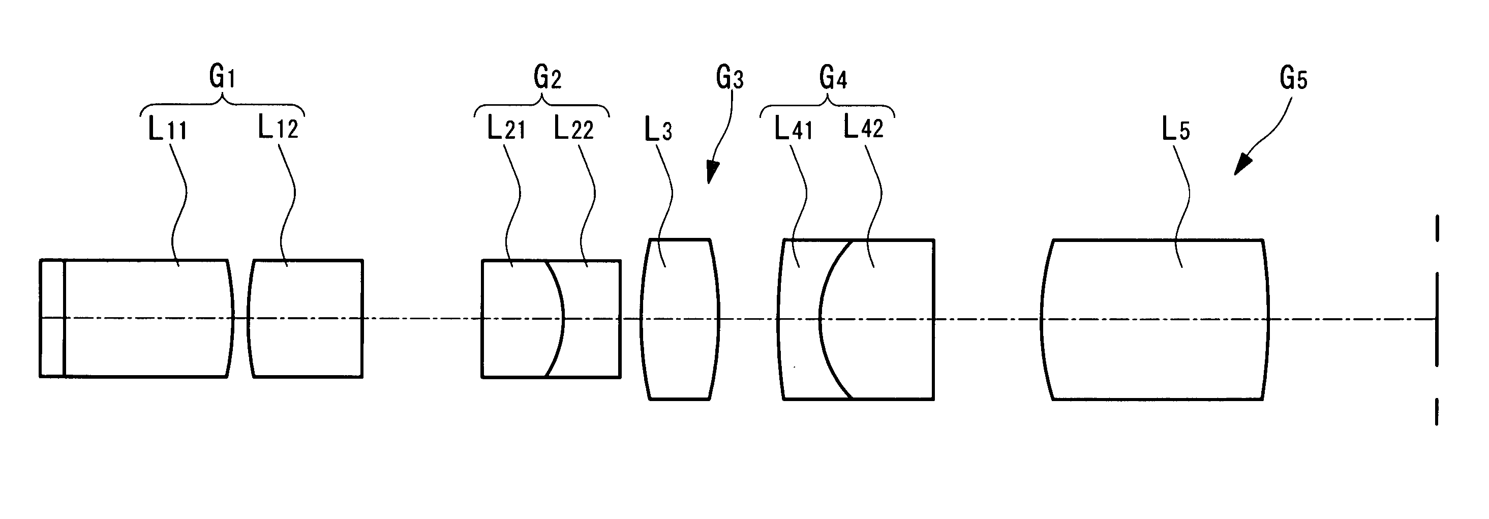
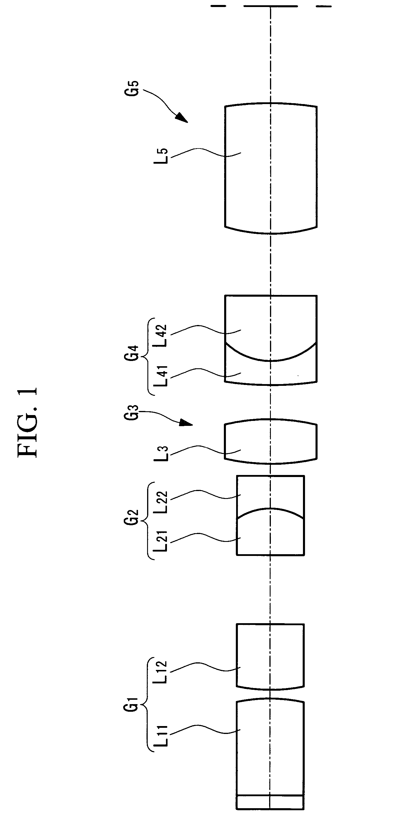
[0120]FIG. 4 shows the lens arrangement of a first Example of the compact objective optical system 1, and Table 1 shows lens data of the compact objective optical system 1 according to this Example. FIGS. 5A to 5F show aberration plots for the compact objective optical system 1 of this Example. FIG. 5A shows spherical aberration, FIG. 5B shows astigmatism, FIG. 5C shows distortion, FIG. 5D shows lateral chromatic aberration, and FIGS. 5E and 5F show comatic aberrations. In FIGS. 5A to 5F, symbol NA indicates the numerical aperture at the image side, symbol y indicates the image height, symbol M indicates the meridional plane, and symbol S indicates the sagittal plane. The lateral chromatic aberration shown in FIG. 5 is based on the d-line (587.56 nm).

[0121]

TABLE 1SURFACENUMBERrdnν1∞0.21.3330455.89(OBJECT(WATER)SURFACE)2∞1.511.5163364.143−3.0020.13142.25611.613444.275∞1.0816∞0.711.4387594.937−0.9420.51.613444.278∞0.2192.9080.71.5163364.1410−2.9080.551114.8270.361.772549.6120.94211.67...

second example

[0125]Next, a second Example of the compact objective optical system 1 will be described below.

[0126]FIG. 6 shows the lens arrangement of the compact objective optical system 1 according to this Example, and Table 2 shows the lens data of the compact objective optical system 1 according to this Example. FIGS. 7A to 7F are aberration plots for the compact objective optical system 1 of this Example. FIG. 7A shows the spherical aberration, FIG. 7B shows astigmatism, FIG. 7C shows distortion, FIG. 7D shows lateral chromatic aberration, and FIGS. 7E and 7F show comatic aberrations. The symbols in FIGS. 7A to 7F are the same as those in the first Example.

[0127]

TABLE 2SURFACENUMBERrdnν1∞0.21.3330455.89(OBJECT(WATER)SURFACE)2∞1.661.5163364.143−3.1020.33143.2812.51.613444.275∞0.1516∞11.4387594.937−0.9420.511.613444.278INF0.4193.1020.71.5163364.1410−3.1020.551111.9610.361.772549.6120.94211.5163364.1413∞0.99114∞1.51.5163364.1415−2.3851.43116∞(IMAGINARYSURFACE)

[0128]The compact objective optica...

third example

[0131]Next, a third Example of the compact objective optical system 1 will be described below.

[0132]FIG. 8 shows the lens arrangement of the compact objective optical system 1 according to this Example, and Table 3 shows the lens data for the compact objective optical system 1 according to this Example. FIGS. 9A to 9F show aberration plots for the compact objective optical system 1 of this Example. FIG. 9A shows spherical aberration, FIG. 9B shows astigmatism, FIG. 9C shows distortion, FIG. 9D shows lateral chromatic aberration, and FIGS. 9E and 9F show comatic aberrations. The symbols in FIGS. 9A to 9F are the same as those in the first Example.

[0133]

TABLE 3SURFACENUMBERrdnν1∞0.11.3330455.79(OBJECT(WATER)SURFACE)2∞0.341.5163364.143∞(PRISM)11.772549.64∞0.51.772549.65−4.480.13162.25611.613444.277∞1.0818∞0.711.4387594.939−0.9420.51.613444.2710∞0.21112.9080.71.5163364.1412−2.9080.551134.8270.361.772549.6140.94211.677955.3415∞0.991162.53221.5163364.1417−8.4561.51118∞(IMAGINARYSURFACE)

[0...


PUM


Abstract

By reducing the outer diameter, increasing the overall length, and correcting chromatic aberration well, the invention realizes an objective optical system and examination apparatus that are suitable for in-vivo examination with a sufficiently increased length and widened observation range. The invention provides a compact objective optical system and an examination apparatus comprising, in order from an object side: a first lens group having positive power; a second lens group including a compound lens; a third lens group formed of a biconvex lens; a fourth lens group having positive power and including a compound lens; and a fifth lens group having positive power. Joining surfaces of the compound lens included in the second lens group and the compound lens included in the fourth lens group have negative power.

Description

BACKGROUND OF THE INVENTION[0001]1. Field of the Invention[0002]The present invention relates to a compact objective optical system having a long, thin shape and to an examination apparatus using the same, and more particularly, to an optical system that is inserted into an animal such as a mammal to perform in-vivo examination at high resolution and to an examination apparatus using the same.[0003]This application is based on Japanese Patent Application No. 2005-041130, the content of which is incorporated herein by reference.[0004]2. Description of Related Art[0005]There are techniques in which a dye or fluorescent marker is attached to specific molecules, tissue, cells, and so on and fluorescence microscopes, confocal laser-scanning microscopes, and the like are used to examine the behavior of the molecules in the cells and tissue of living organisms.[0006]The behavior of molecules in a live individual mammalian organism, such as a mouse, may differ from that in cultured cells. T...

Claims


Application Information

Patent Timeline
Patent Type & Authority Patents(United States)
IPC IPC(8): G02B21/02
CPCG02B23/2446G02B23/243G02B21/16
Inventor HIRATA, TADASHI
Owner EVIDENT CORP
Why Eureka
Try Eureka