Extended cavity laser device with bulk transmission grating

a laser device and bulk transmission technology, applied in the direction of laser optical resonator construction, laser details, optical resonator shape and construction, etc., can solve the problems of grating also leading to angular sweep of output beam, reducing power, and reducing the effect of laser radiation

Active Publication Date: 2007-02-13
LUMENTUM OPERATIONS LLC
View PDF26 Cites 27 Cited by
  • Summary
  • Abstract
  • Description
  • Claims
  • Application Information

AI Technical Summary

Benefits of technology

[0020]In accordance with the invention, a Littrow-stabilized laser apparatus is provided comprising a laser diode having a reflective back facet and a front facet having a reflectance of less than 1% for emitting an optical beam at a fundamental frequency along an optical path, collimating means for at least partially collimating the optical beam into an at least partially collimated beam along the optical path, a transmission grating in a Littrow-type arrangement optically coupled to receive the at least partially collimated beam and for returning a portion of the at least partially collimated beam back into the laser diode by means of diffraction through the collimating means and the laser diode front facet, wherein the laser diode reflective back facet and the transmission grating form an extended laser cavity, and wherein in operation, at least a substantial portion of the at least partially collimated beam is transmitted through the transmission grating for producing the laser output beam propagating along the optical path, with a direction of the laser output beam being substantially angle...

Problems solved by technology

Furthermore, since complex laser designs usually lead to somewhat reduced power, these prior art solutions either use an intra-cavity nonlinear doubling arrangement to benefit from the intra-cavity resonance power enhancement, at the expense of yet more complex cavity control, or use single-pass doubling with relatively low output powers
However, the low optimal feedback requirements of ˜3% required for high-power lasers make the intra-cavity placement of the nonlinear SHG element an unnecessary complication.
The drawback of a conventional Littrow cavity design described above for an outer-cavity arrangement of the nonlinear element is that the rotation of the reflective grating also lea...

Method used


Image

  • Extended cavity laser device with bulk transmission grating
  • Extended cavity laser device with bulk transmission grating
  • Extended cavity laser device with bulk transmission grating

Examples


Embodiment Construction

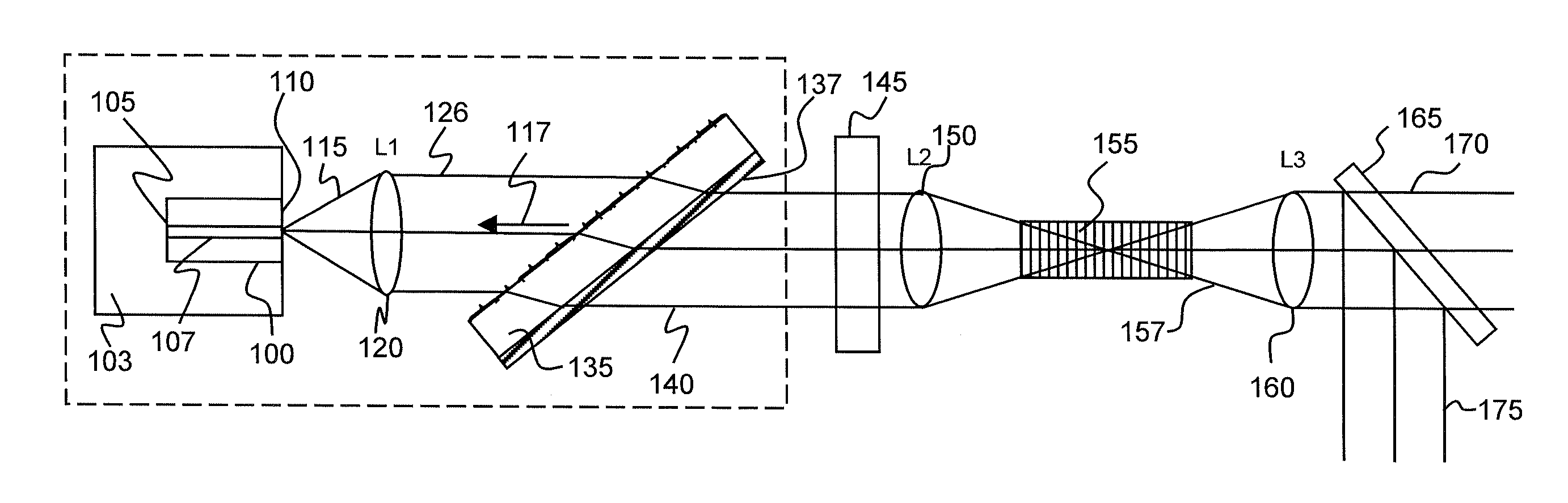
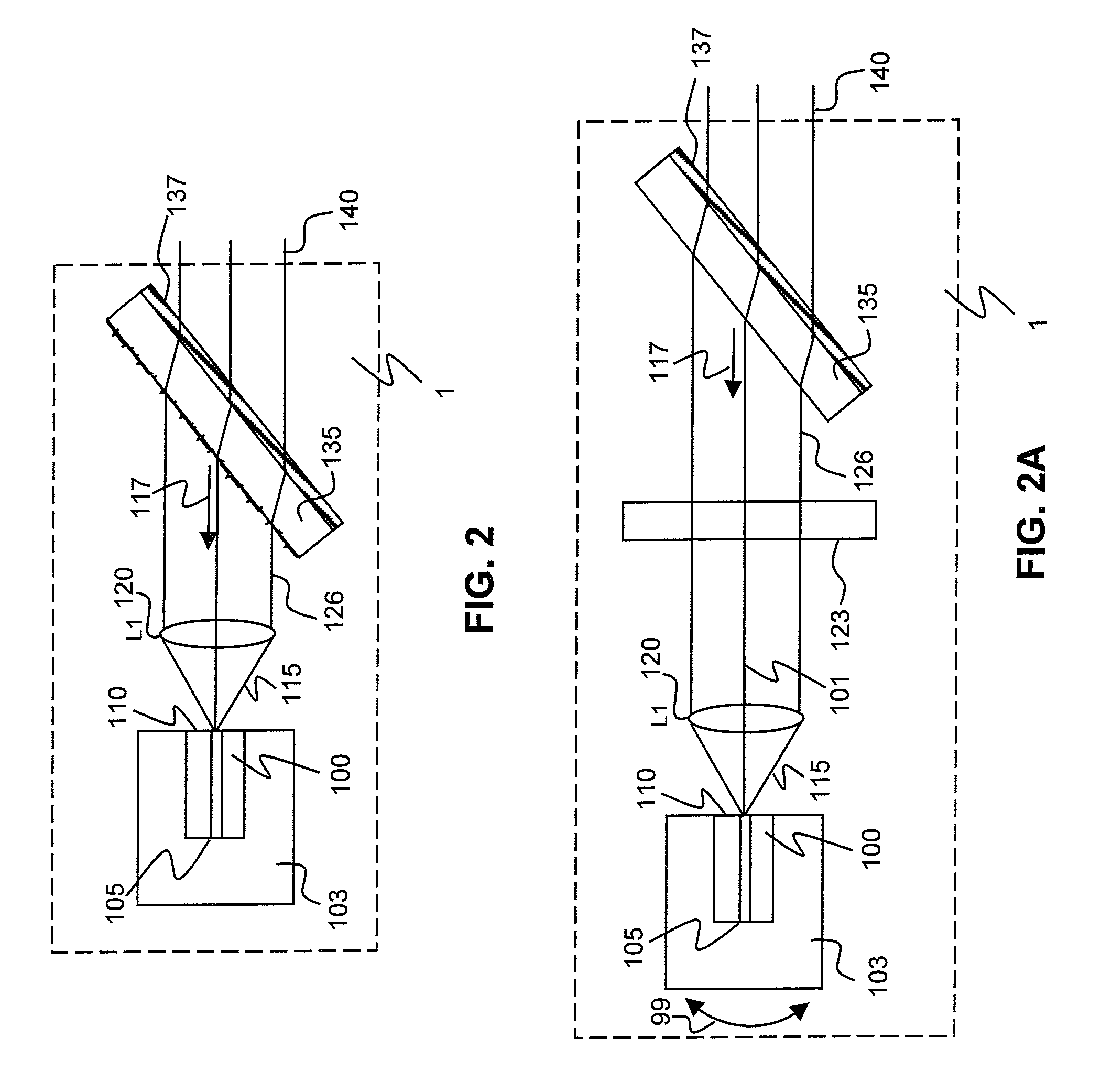
[0036]A preferred embodiment of a Littrow-stabilized laser diode using a transmission grating is shown in FIG. 2 and is hereafter described.

[0037]A semiconductor laser diode chip 100 mounted on a carrier 103 has a high-reflection coated back facet 105 and an anti-reflection coated front facet 110. The laser diode is capable of emitting a high power coherent light beam 115 in a single spatial mode having a wavelength in the red or near-infrared region of the optical spectrum. The laser diode is optically coupled through a collimating means 120 to a bulk diffraction grating 135. The collimating means 120 at least partially collimates the light beam 115 to form a beam 126 hereinafter referred to as the at least partially collimated laser diode beam 126, or simply as the laser diode beam 126. The bulk diffraction grating 135 is oriented to diffract a portion of the laser diode beam 126 back into the laser diode to provide optical feedback, as schematically shown by an arrow 117. The col...


PUM


Abstract

A laser apparatus is disclosed utilizing a laser diode having a reflective back facet and a front facet having a reflectance of less than about 1% for emitting an optical beam at a fundamental frequency along an optical path. A collimating lens is provided for collimating the optical beam into a collimated beam. A transmission grating is optically coupled to receive the collimated beam and returns a portion of the collimated beam back into the laser diode by means of diffraction through lens and the laser diode front facet. The laser diode reflective back facet and the transmission grating form an extended laser cavity. In operation, a substantial portion of the collimated beam is transmitted through the transmission grating for producing the laser output beam propagating along the optical path.

Description

CROSS-REFERENCE TO RELATED APPLICATIONS[0001]This application claims priority of U.S. Provisional Patent Application No. 60 / 423,740 filed Nov. 5, 2002, entitled “Blue Frequency-Doubled Diode Laser Configuration” which is incorporated herein by reference for all purposes.FIELD OF THE INVENTION[0002]The present invention relates to sources of laser radiation and their optical stabilization. This invention is particularly suitable for sources of short-wavelength radiation employing frequency doubling of laser diode emission in external cavity configurations.BACKGROUND OF THE INVENTION[0003]There is considerable demand for short-wavelength laser sources such as green, blue and UV lasers. One known approach to create such a light source is to utilize red or infra-red laser diodes, which are widely available in a variety of configurations. These diodes, in combination with nonlinear elements made of optically nonlinear materials, can produce short-wavelength frequency-doubled radiation by...

Claims


Application Information

Patent Timeline
IPC IPC(8): H01S3/10H01S3/08H01S5/0687H01S5/14H01S5/323
CPCH01S5/141H01S5/0687H01S5/0092H01S5/32341H01S3/1055H01S5/143
Inventor LANG, ROBERT J.WAARTS, ROBERT G.
Owner LUMENTUM OPERATIONS LLC
Why Eureka
Try Eureka