DDR on-the-fly synchronization

Active Publication Date: 2007-02-13
HYDAC PROCESS TECH +1
View PDF35 Cites 18 Cited by
  • Summary
  • Abstract
  • Description
  • Claims
  • Application Information

AI Technical Summary

Problems solved by technology

Moreover, due to variations in architectures, strobe signals and data signals may not arrive at a synchronization circuit exactly simultaneously, requiring configurable synchronization circuits.
Such strobe signal delay to configure a synchronizer preclude

Method used


Image

  • DDR on-the-fly synchronization
  • DDR on-the-fly synchronization
  • DDR on-the-fly synchronization

Examples


Embodiment Construction

[0012]FIGS. 1 through 3A–3B, discussed below, and the various embodiments used to describe the principles of the present invention in this patent document are by way of illustration only and should not be construed in any way to limit the scope of the invention. Those skilled in the art will understand that the principles of the present invention may be implemented in any suitably arranged device.

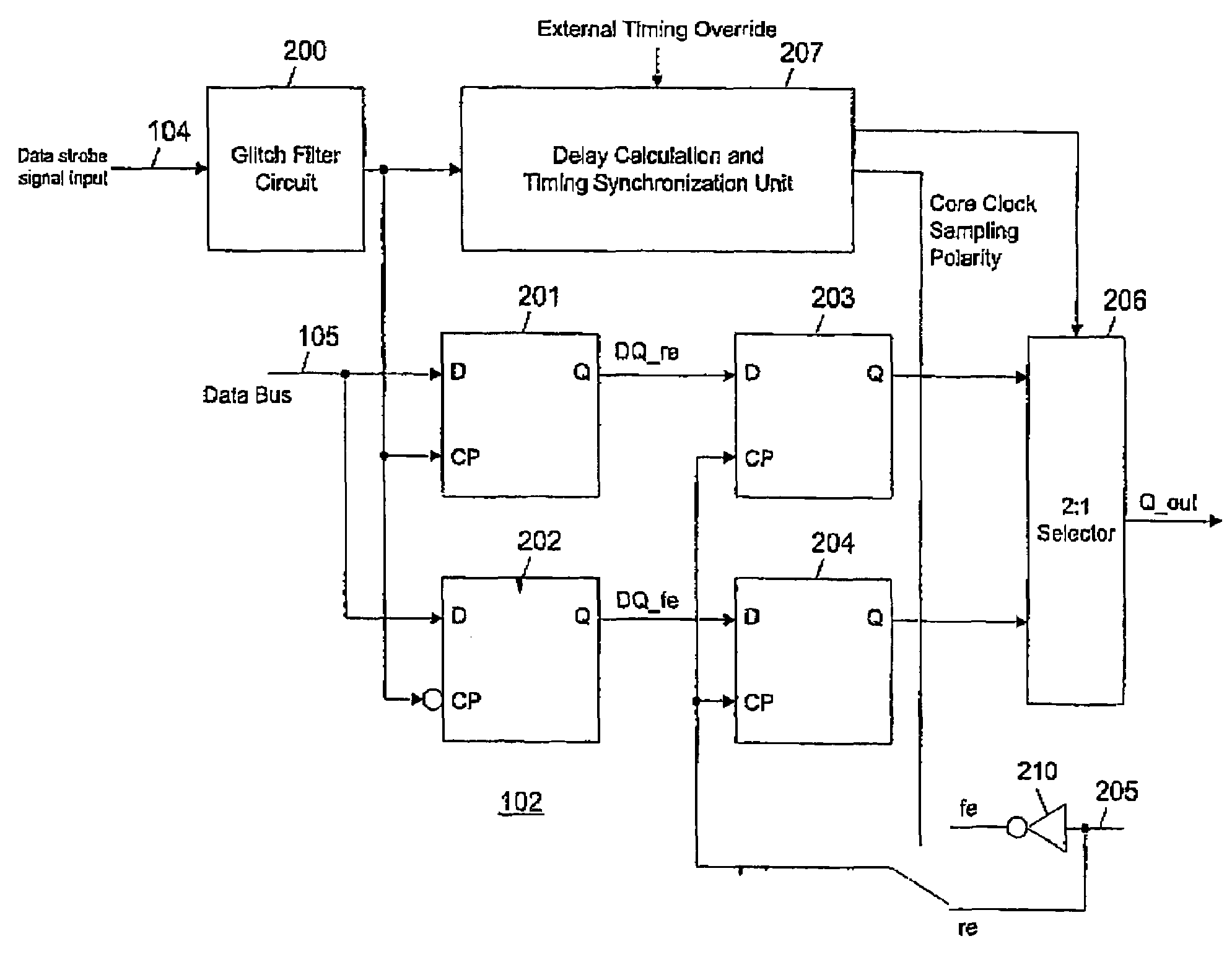
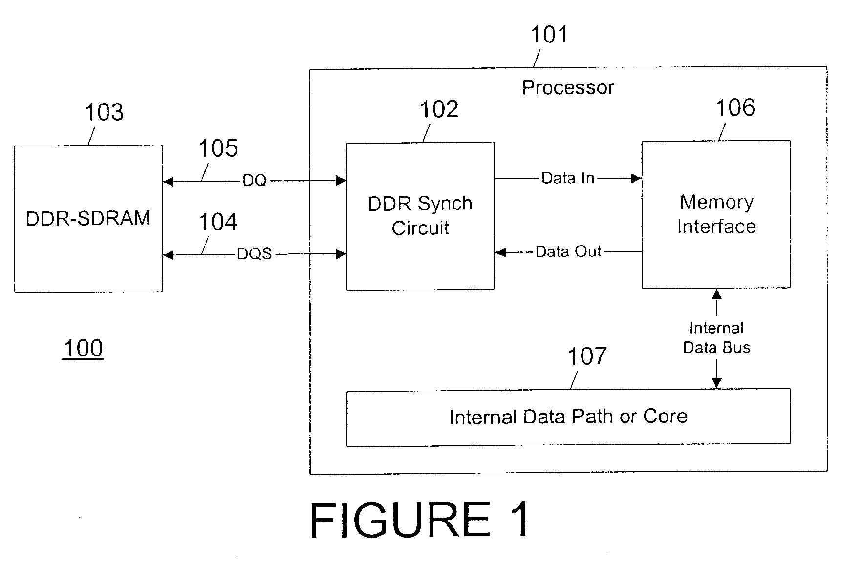
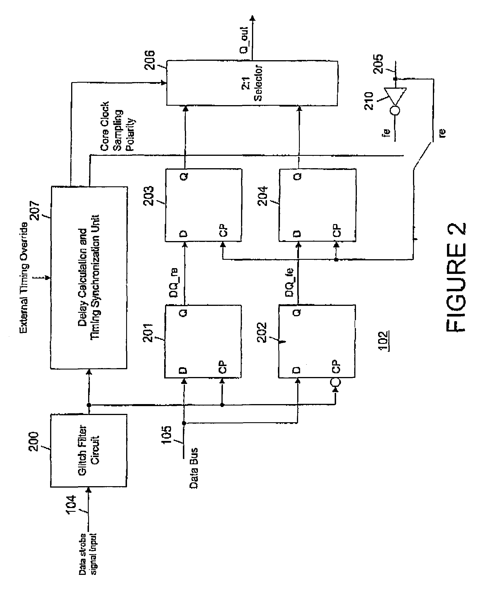
[0013]FIG. 1 depicts a data processing system including a configurable synchronizer according to one embodiment of the present invention. Those skilled in the art will recognize that the full construction and operation of a data processing system is not depicted or described herein. Instead, for simplicity and clarity, only so much of the construction and operation of a data processing system as is unique to the present invention or necessary for an understanding of the present invention is depicted and described.

[0014]Data processing system 100 includes a processor 101 coupled, via an inte...


PUM


Abstract

Double data rate (DDR) synchronous dynamic random access memory (SDRAM) data is sampled into a synchronization circuit on both rising and falling edges of a data strobe (DQS) signal, into separate latches. A delay calculation and timing synchronization unit determines the location of the data strobe signal relative to rising/falling edges of an internal clock, then decides which sample to transfer into the internal data path and whether to use the rising or falling internal clock edge. Every DDR-SDRAM read transaction is thus automatically synchronized without the need for predetermined delay(s), allowing a wide range of operating frequencies and frequency variations to be accommodated.

Description

TECHNICAL FIELD OF THE INVENTION[0001]The present invention is directed, in general, to memory synchronization and, more specifically, to configurable synchronization of each memory transaction to permit operation at a wide range of frequencies.BACKGROUND OF THE INVENTION[0002]Double data rate (DDR) synchronous dynamic random access memory (SDRAM) allows data to be transferred from a memory to a processor or bus on both the rising and falling edges of a clock signal. Within DDR-SDRAM systems, data strobe signals (DQS) are transmitted (at least nominally) synchronously with the data bus signals (DQ), but asynchronously with respect to the clock controlling the receiving processor, bus or other receiving device. Accordingly, a synchronization circuit is required to properly receive data from a DDR-SDRAM. Moreover, due to variations in architectures, strobe signals and data signals may not arrive at a synchronization circuit exactly simultaneously, requiring configurable synchronizatio...

Claims


Application Information

Patent Timeline
IPC IPC(8): H04L7/00
CPCH04L7/0338
Inventor SHIHADEH, ELIASVALENCIA, REDENTORKOMMRUSCH, STEVEN
Owner HYDAC PROCESS TECH
Why Eureka
Try Eureka