
Transmission method and network gateway device for real-time communication between packet-oriented communication networks

a technology of packet-oriented communication and transmission method, which is applied in the direction of data switching network, instruments, data processing applications, etc., can solve the problems of high processor power and the normal cost of corresponding specification of terminal devices for real-time compression of communication data

Inactive Publication Date: 2007-02-13
UNIFY GMBH & CO KG
View PDF11 Cites 58 Cited by
  • Summary
  • Abstract
  • Description
  • Claims
  • Application Information

AI Technical Summary

Benefits of technology

[0005]One possible object of the present invention is to indicate a transmission method and a network gateway device for real-time communication between packet-oriented communication networks, whereby the technical outlay required to compress and / or decompress real-time communication data which are to be transmitted is reduced compared with the state of the art.
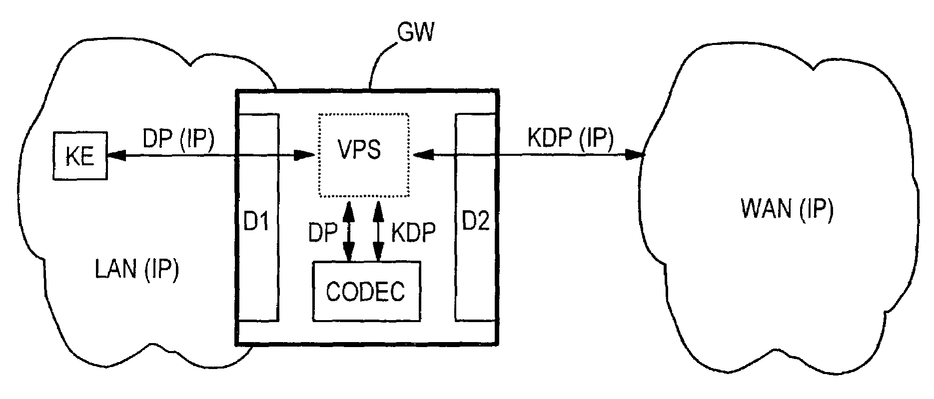
[0010]In a typical application, the above method and device provide to be particularly advantageous, the first communication network is designed, for example, as a local area network with a high transmission bandwidth and the second communication network, for example, is designed as a wide area network with relatively meager transmission resources. Since a local area network normally has a very high transmission bandwidth, the additional transmission bandwidth which is required due to essentially uncompressed transmission of the data packets from the communication terminal device to the data compression device can usually be ignored or at least accepted. Following the compression of the data packets, the latter are forwarded into the wide area network where, due to the compression, only a narrow transmission bandwidth is occupied. Due to the compression or decompression of the data packets in a data compression device or data decompression device disposed in the first communication network and preferably in a network gateway device to the second communication network, no costly implementation of a compression or decompression function in each individual communication terminal device of the first communication network is required. The processor power required in a respective communication terminal device is thereby considerably reduced. In addition, if compression methods subject to a license fee are used, a license is no longer required for each individual communication terminal device. The number of required licenses is determined instead by the substantially lower maximum number of real-time communication connections which can be set up simultaneously from the first communication network into an external communication network.
[0011]A further advantage is that many communication services, for example conference circuits or speech recognition, process essentially uncompressed communication data and can therefore be incorporated more easily into the first communication network if the communication data is transmitted in essentially uncompressed form therein.
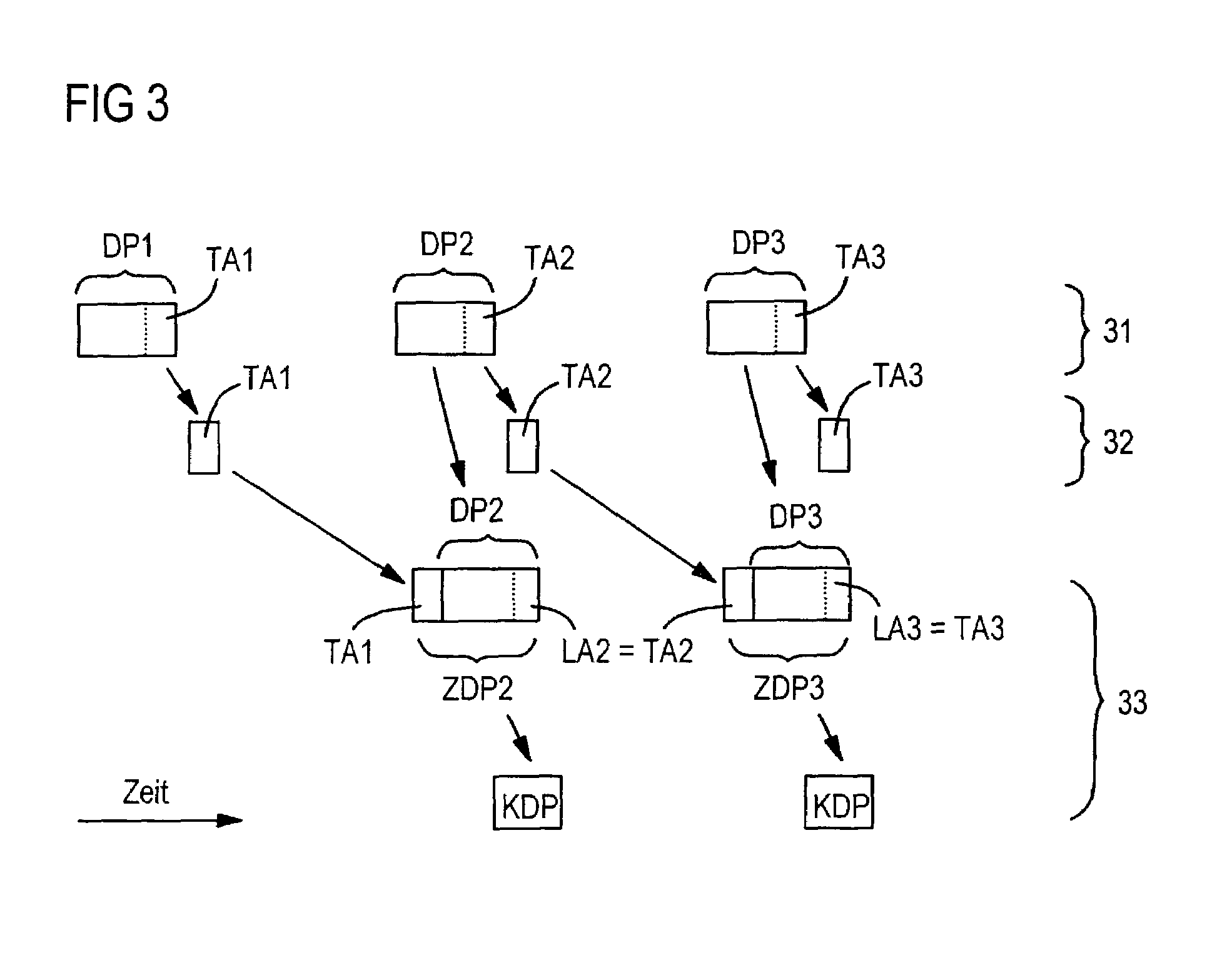
[0013]According to a further advantageous development, a communication data stream which is to be transmitted during the real-time communication can be divided up by the communication terminal device among the data packets in such a way that communication data stream segments inserted into consecutive data packets partially overlap one another. This offers the advantage that a respective data packet with the communication data stream segment inserted therein can be compressed by the data compression device on an individual packet basis, i.e. independently from other data packets, by a prediction compression method. The subsegment of this segment which overlaps a communication data stream segment inserted into a following data packet can be used as a “look-ahead” for the prediction compression method. Modern prediction compression methods enable a very high compression rate, but, in order to compress communication data of a predefined time interval, also require communication data which temporally follow the time interval which is to be compressed. These communication data temporally following the time interval are referred to as a look-ahead or algorithmic look-ahead. On the basis of the overlap of the communication data stream segments contained in the data packets, the overlapping subsegment can be used in each data packet as a look-ahead for the prediction compression method, so that each data packet can be individually compressed without first having to wait for a following data packet due to a required look-ahead. In this way, a delay caused by the compression can be substantially reduced. Such a transport of overlapping communication data stream segments can preferably be provided as a new user data type for the “RTP protocol” (RTP: Real Time Protocol).

Problems solved by technology

However, such real-time compression of communication data requires a relatively high processor power which is to be delivered by the terminal device concerned.
A corresponding specification of the terminal devices is therefore normally relatively costly.

Method used


Image

  • Transmission method and network gateway device for real-time communication between packet-oriented communication networks
  • Transmission method and network gateway device for real-time communication between packet-oriented communication networks
  • Transmission method and network gateway device for real-time communication between packet-oriented communication networks

Examples


Embodiment Construction

Reference will now be made in detail to the preferred embodiments of the present invention, examples of which are illustrated in the accompanying drawings, wherein like reference numerals refer to like elements throughout.

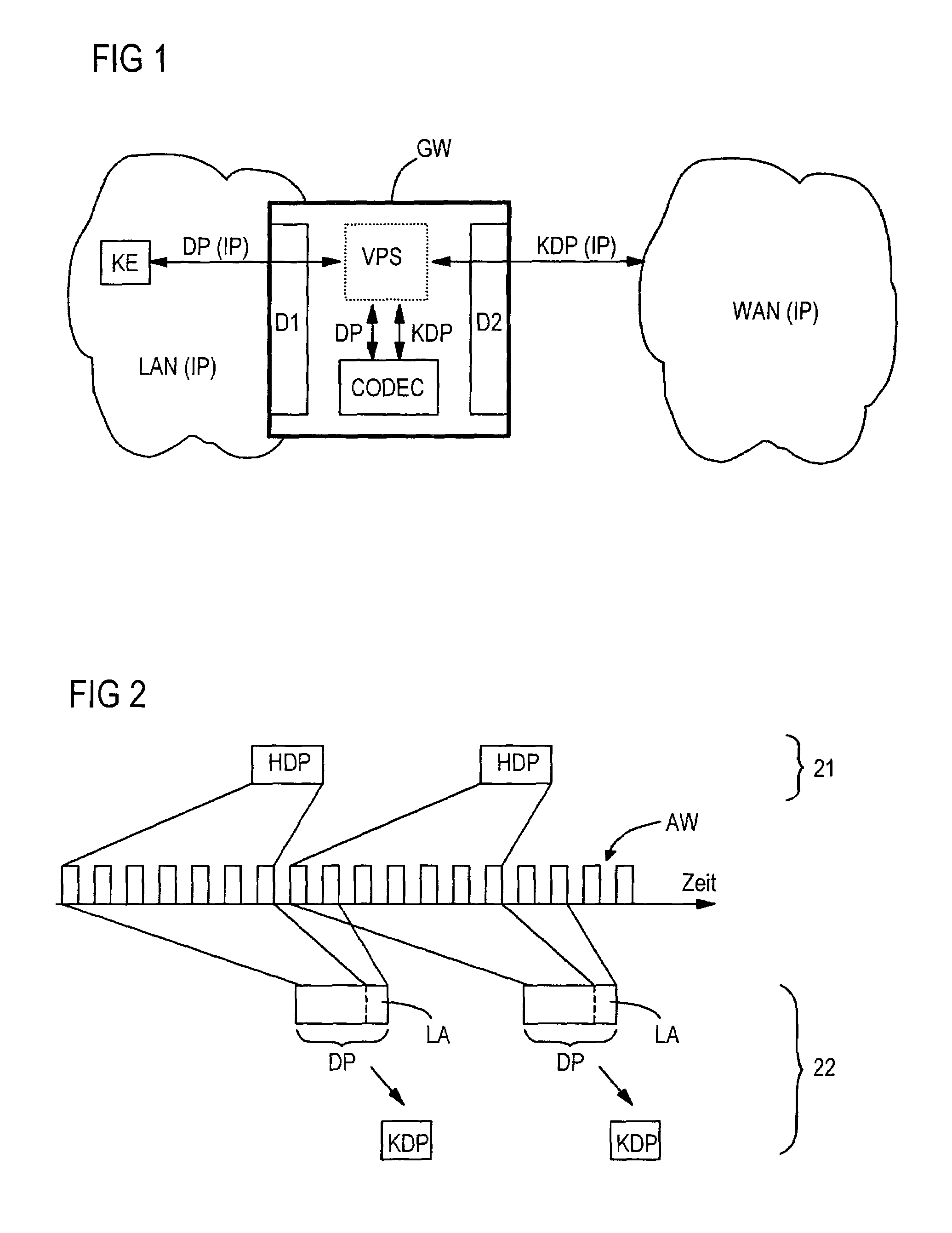
[0019]FIG. 1 schematically shows a packet-oriented communication system, in which a local area network LAN is connected via a network gateway device designed as a gateway GW to a wide area network WAN, e.g. the Internet, for voice, video and / or multimedia real-time communication. Both the local area network LAN and the wide area network WAN are packet-oriented communication networks, i.e. a respective data transport is based on asynchronously transmitted data packets. In the present embodiment, the data packets are transported in both communication networks LAN and WAN by the “Internet Protocol” IP, onto which higher transmission protocols, e.g. UDP (User Datagram Protocol) or TCP (Transmission Control Protocol) can be overlaid.

[0020]The local area network LAN has ...


PUM


Abstract

In real-time communication between a communication terminal device of a first packet-oriented communication network and a second packet-oriented communication network, data packets which are to be transmitted are transmitted from the communication terminal device in essentially uncompressed form via the first communication network to a data compression device, in order to be compressed before being forwarded into the second communication network.

Description

CROSS REFERENCE TO RELATED APPLICATIONS[0001]This application is based on and hereby claims priority to German Application No. 101 47 979.4 filed on Sep. 28, 2001, the contents of which are hereby incorporated by reference.BACKGROUND OF THE INVENTION[0002]In present-day communication systems, real-time connections are also increasingly set up, e.g. for voice, video or multimedia communication, via packet-oriented communication networks, such as local area networks (LAN) or wide area networks (WAN). “Internet telephony”, for example, also frequently referred to as VoIP telephony (VoIP: Voice / Video over Internet Protocol), is based on this technology.[0003]Known terminal devices for packet-oriented real-time communication normally have a “coder” (codec), e.g. in accordance with ITU-T Recommendations G.729 or G.723.1, which, in real time, compresses the real-time communication data which are to be transmitted and transfers them in the form of data packets into a packet-oriented communi...

Claims


Application Information

Patent Timeline
IPC IPC(8): G06F15/173H04L12/46H04L29/06H04L29/08H04M7/00
CPCH04L12/4612H04L29/06H04L69/04H04L65/607H04L29/06027H04M7/006Y10S707/99955H04L69/329Y10S707/99953H04L65/70H04L9/40H04L65/1101
Inventor KRAMER, RICHARD
Owner UNIFY GMBH & CO KG
Learn More