
Process/viewer interface

a viewer interface and process technology, applied in the field of graphical user interfaces, can solve the problems of inconvenient user work efficiency, inconvenient mdi or dialog window dependent systems residing in the inconsistency of control and data location, so as to simplify window management, simplify window management, and reduce screen clutter

Active Publication Date: 2007-02-13
PEGASYSTEMS
View PDF40 Cites 148 Cited by
  • Summary
  • Abstract
  • Description
  • Claims
  • Application Information

AI Technical Summary

Benefits of technology

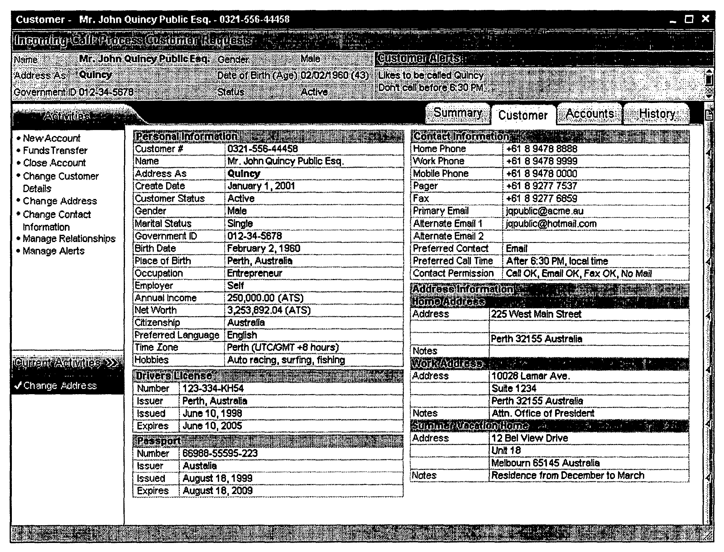
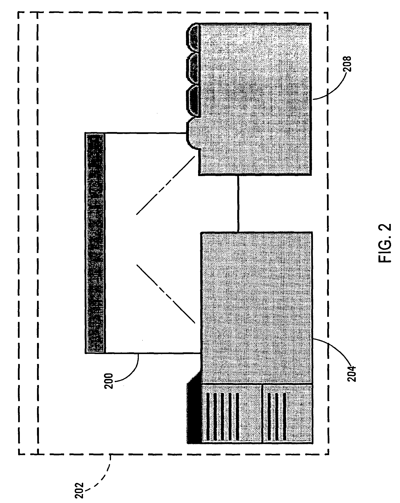
"The present invention provides a user interface for viewing and manipulating data associated with a conceptual object in a single window. The interface includes a process panel for executing complex processes and a data viewer for displaying reference data. The process panel and data viewer are arranged in an overlapping manner within a common window, which simplifies window management and reduces screen clutter compared to traditional applications. The invention also provides a consistent location of on-screen controls and data, making it easier for users to navigate the interface. Overall, the invention simplifies the viewing and management of complex objects and is suitable for thin client web applications."

Problems solved by technology

A significant disadvantage of MDI or dialog window dependent systems resides in the inconsistency of control and data location.
Even if the location of the related windows were relatively consistent when first open, the user may move, resize, or reorder them in the z axis at anytime, potentially making them more difficult to locate later.
When multiple MDI windows must be referenced repeatedly, as in viewing reference data in one while working in another, it becomes awkward for the user to work efficiently and can be confusing.
Modal dialogs have generally been used because of the difficulties inherent in management of non-modal dialogs that impact the calling parent window.

Method used


Image

  • Process/viewer interface
  • Process/viewer interface
  • Process/viewer interface

Examples


Embodiment Construction

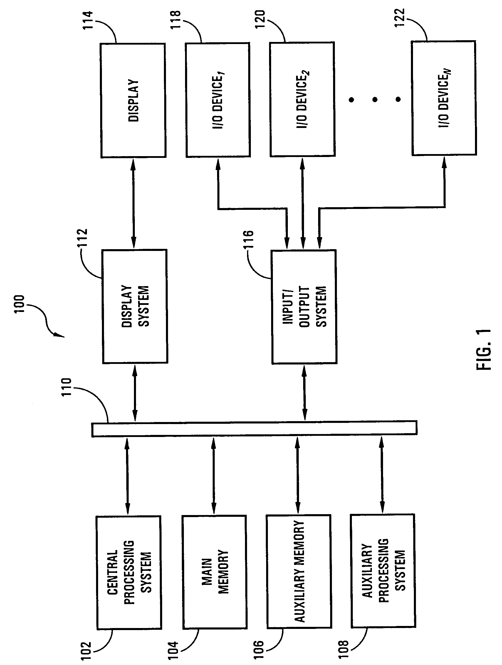
[0030]Referring now to FIG. 1, an information handling system operable to embody the present invention is shown. The hardware system 100 shown in FIG. 1 is generally representative of the hardware architecture of a computer-based information handling system of the present invention, such as the client computer system 912 or the server computer system 940 of the networked system 900 shown in FIG. 9. The hardware system 100 is controlled by a central processing system 102. The central processing system 102 includes a central processing unit such as a microprocessor or microcontroller for executing programs, performing data manipulations and controlling the tasks of the hardware system 100. Communication with the central processor 102 is implemented through a system bus 110 for transferring information among the components of the hardware system 100. The bus 110 may include a data channel for facilitating information transfer between storage and other peripheral components of the hardw...


PUM


Abstract

A user interface for viewing reference data associated with a conceptual entity and for execution of one or more complex processes for manipulating the data includes a process panel having one or more on-screen objects for the execution of the complex processes and a process work area for displaying a state of selected complex processes. A data viewer includes a content pane for the display of the reference data and one or more on-screen objects for selectively displaying at least a portion of the reference data and the process panel and data viewer are framed within a common window. The process panel and data viewer are selectably viewable and occupy overlapping positions within the common window.

Description

FIELD OF THE INVENTION[0001]The present invention relates generally to a graphical user interface and, more particularly, to a combined process interface and data viewer interface (“process / viewer interface” or “PVI”) that allows users, in a single window, to (1) execute and display one or more complex processes against some conceptual object or entity represented in software, and (2) to view reference data related to that conceptual object in an data viewer mechanism.[0002]Unless indicated otherwise, the term “conceptual object” as used herein refers not to a data object, but to a conceptual entity that can be represented in a software model and has properties or characteristics that may need to be interrogated, and has associated processes that may be run against it. In a preferred aspect, the present invention finds particular application for use in connection with software for customer call centers or other points of customer contact such as retail branch outlets, mobile setting...

Claims


Application Information

Patent Timeline
Patent Type & Authority Patents(United States)
IPC IPC(8): G06F3/048G06F9/44G06F17/00H04N
CPCG06F9/4443G06F9/451
Inventor HEWSON, DARREN M.ST. JEAN, JAMES D.MYLES, J. MICHAELRUGGIERI, JR., MICHAEL J.
Owner PEGASYSTEMS
Learn More