Cargo handling apparatus

Inactive Publication Date: 2007-02-20
ROSS RALPH BARCLAY
View PDF19 Cites 1 Cited by
  • Summary
  • Abstract
  • Description
  • Claims
  • Application Information

AI Technical Summary

Benefits of technology

[0008]Thus, the present invention enables a compression force to be applied to the packaged elongate members by adjustment of the tension member, which causes the pressure plate to be urged against the frame.
[0009]Preferably the pressure plate is provided with two ends, and an engaging means is located at each end of the pressure plate. This enables pressure to be applied over the length of the pressure plate, and hence more evenly across the elongate membe

Problems solved by technology

However, currently-known retaining arrangements are often unwieldy and may be difficult to fix correctly; further, existing retaining arrangements do not avoid the pos

Method used


Image

  • Cargo handling apparatus
  • Cargo handling apparatus
  • Cargo handling apparatus

Examples


Embodiment Construction

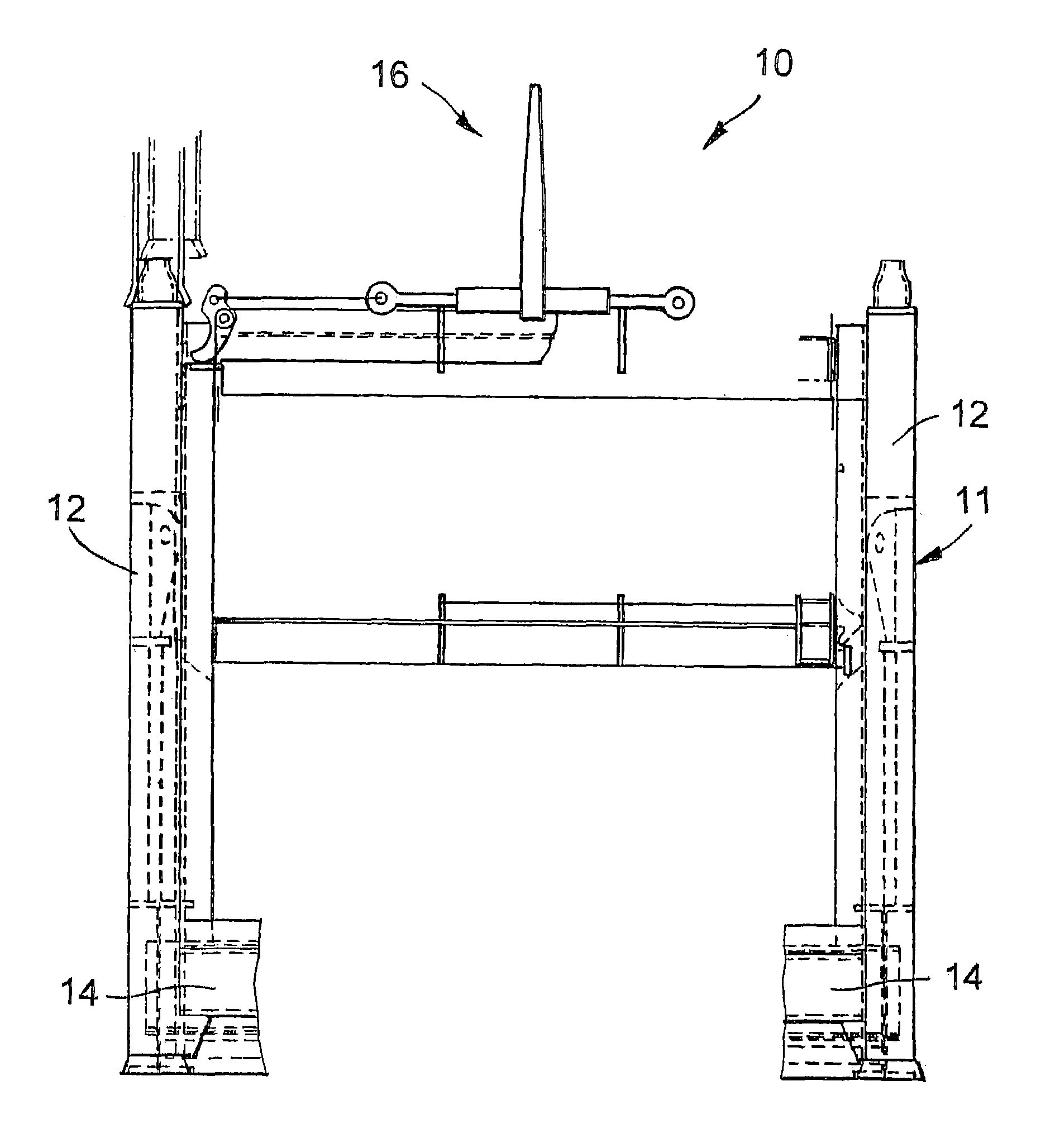
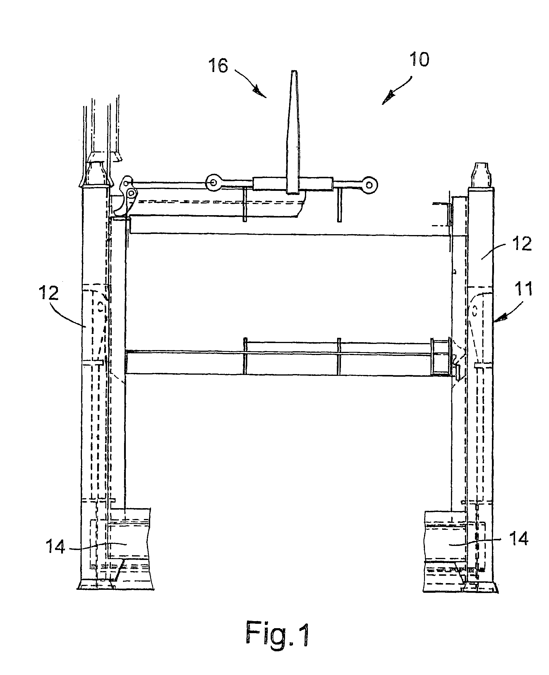
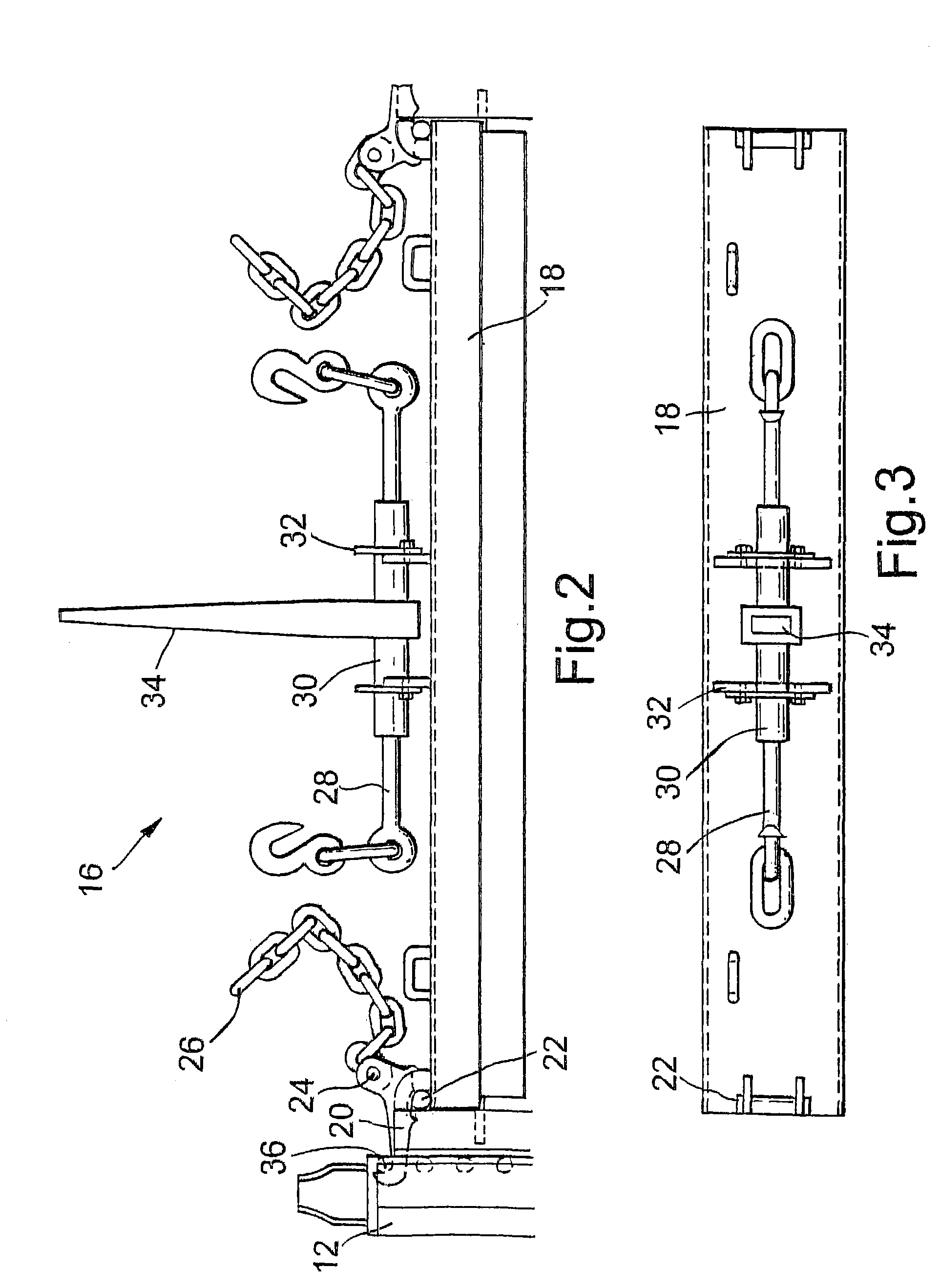
[0036]Referring first of all to FIG. 1, this shows a partial sketch of an apparatus for packaging elongate members, in accordance with one embodiment of the invention. The apparatus 10 includes a pair of U-shaped frame members 11 (only one shown in end view), comprising two upright side portions 12 connected by an elongate base member 14 (only partially shown). Each of the U-shaped frame members has a number of horizontally-extending cross-pieces (not shown) extending between the upright portions of the U-frame 12. Each of the cross-pieces is covered with a profiled cover of a deformable resilient elastomeric compound. In use, sections of drillpipe may be loaded onto the apparatus, with a cross-piece supporting either end of the pipe. The elastomeric compound deforms under the weight of the pipe, to hold the pipe securely in position. A number of layers of pipe may be built up, with elastomer on the lower portions of the cross-pieces engaging the upper surfaces of the lower layers o...


PUM


Abstract

A retaining member 16 is provided for use with a frame 10 for packaging elongate members, such as sections of drill pipe. The retaining member 16 comprises a pressure plate 18 on which is mounted a pair of pivoting hooks 20 for engaging with protrusions 36 formed on the frame 10. The hooks 20 are connected to threaded rods 28 received in a sleeve 30. A ratcheted handle 34 allows selective rotation of the sleeve 30 to draw the rods 28 therein, and to pivot the hooks 20 to urge the pressure plate 18 against members received within the frame 10. A quick release mechanism is provided to allow easy release of the hooks 20 and the retaining member 16.

Description

REFERENCE TO RELATED APPLICATION[0001]This application is a division of U.S. patent application Ser. No. 09 / 911,101 for a “Cargo Handling Apparatus”, filed on Jul. 23, 2001 (now U.S. Pat. No. 6,599,069, which issued on Jul. 29, 2003).FIELD OF THE INVENTION[0002]The present invention relates to cargo handling apparatus, particularly apparatus for packaging elongate members. Aspects of the invention further relate to a retaining member for use in such an apparatus, for retaining elongate members in a packaged state.BACKGROUND OF THE INVENTION[0003]Drilling boreholes by rotary drilling usually involves use of a drill string with a drill bit at the distal end, and a motor at the rig end. The drill string is conventionally made up of many drillpipe sections which are connected together by threaded box and pin connections. The drillpipe sections are typically 9.5–13.1 meters long, are relatively heavy, and require careful handling.[0004]For storing and transporting drillpipe and other tub...

Claims


Application Information

Patent Timeline
IPC IPC(8): B60P7/08B65D85/20B65G1/04
CPCB65G1/0442B65D85/20
Inventor ROSS, RALPH BARCLAY
Owner ROSS RALPH BARCLAY
Why Eureka
Try Eureka