Regenerative autothermal catalytic steam reformer

Inactive Publication Date: 2007-02-20
JOHNSON MATTHEY PLC
View PDF5 Cites 7 Cited by
  • Summary
  • Abstract
  • Description
  • Claims
  • Application Information

AI Technical Summary

Benefits of technology

[0026]The invention has the further object of providing a steam reformer which automatically regenerates itself by removing carbon deposits, and which therefore can be oper

Problems solved by technology

A problem encountered in steam reforming is the deposit of carbon on the reforming catalyst.
Although elemental carbon does not explicitly appear in the equations shown above, it turns out that the steam reforming reaction does produce at least small amounts of carbon which, if allowed to build up, will eventually smother the catalyst and thereby render it useless.
Moreover, to the extent that less than all of the hydrocarbon fuel is converted in the steam reforming reaction, some of the uncon

Method used


Image

  • Regenerative autothermal catalytic steam reformer
  • Regenerative autothermal catalytic steam reformer
  • Regenerative autothermal catalytic steam reformer

Examples


Example

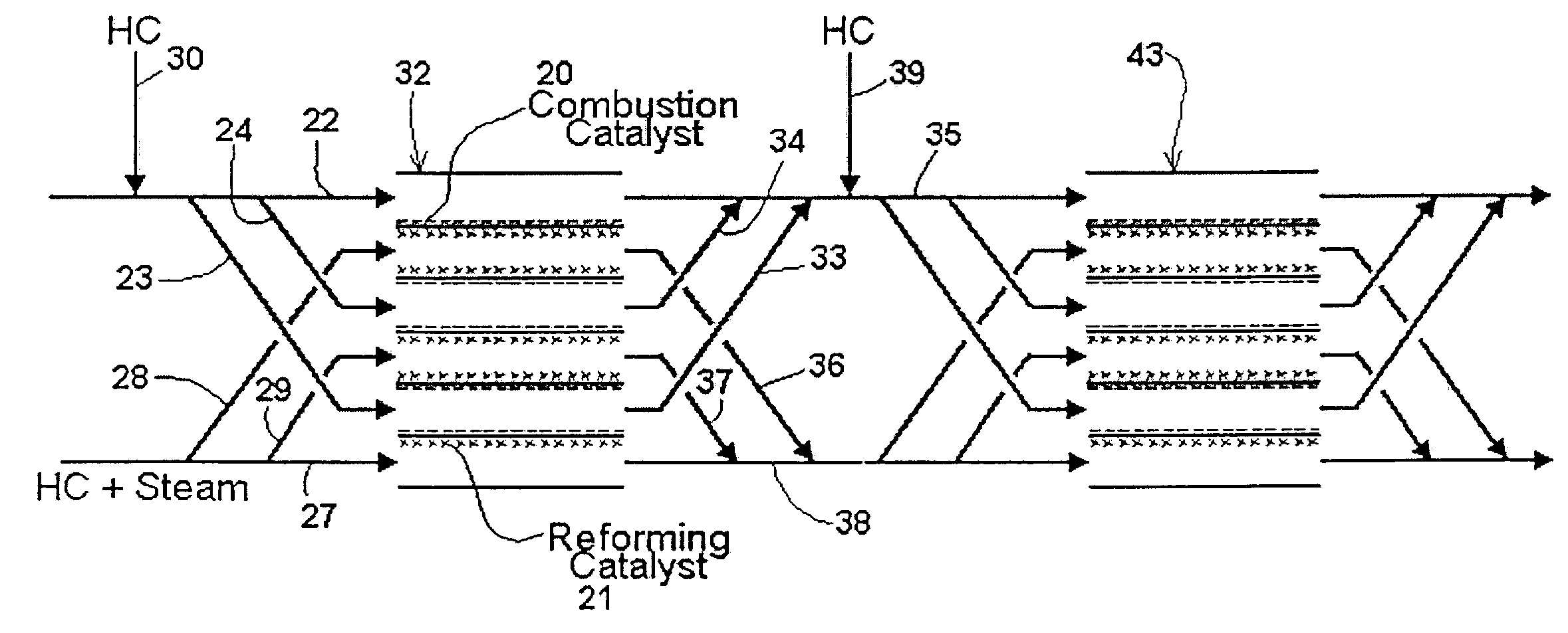
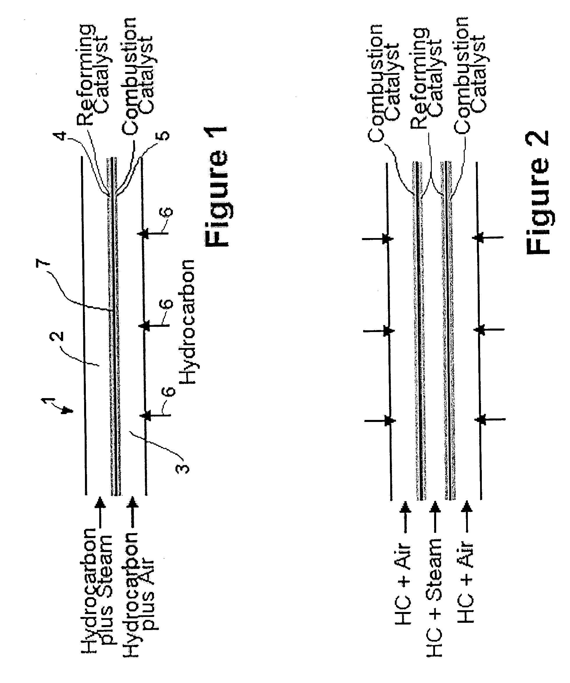
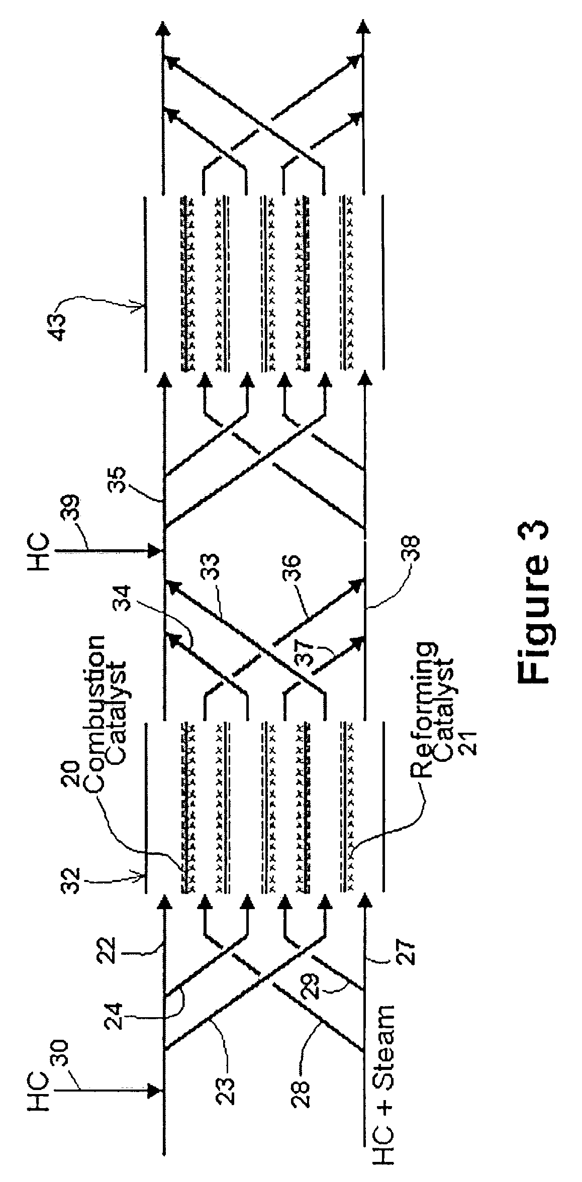
[0038]The simplest form of the invention is shown in the schematic diagram of FIG. 1. Reactor 1 comprises three strips which define two adjacent channels. The first channel 2 is a reforming channel, i.e. it is where the steam reforming reaction occurs. The second channel 3 is a combustion channel.

[0039]In the embodiment shown, the middle strip 7 is coated on one side with reforming catalyst 4, and on the other side with combustion catalyst 5. Thus, first channel 2 has walls which are partially coated with reforming catalyst 4, and second channel 3 has walls which are partially coated with combustion catalyst 5. By “reforming catalyst” is meant a catalyst that promotes the steam reforming reaction discussed above.

[0040]A mixture of a hydrocarbon and steam is injected as shown at the left-hand side of the reforming channel. A mixture of a hydrocarbon and air is injected as shown at the left-hand side of the combustion channel. The hydrocarbon comprises fuel for the combustion.

[0041]Th...


PUM

PropertyMeasurementUnit
Flow rateaaaaaaaaaa
Concentrationaaaaaaaaaa

Abstract

A compact steam reformer produces hydrogen to power a fuel cell, such as can be used in a vehicle. The steam reformer includes a first channel, at least partly coated with a steam reforming catalyst, and a second channel, at least partly coated with a combustion catalyst, the channels being in thermal contact with each other. Heat from the combustion is used in the steam reforming reaction. In another embodiment, the gas streams feeding the reforming and combustion channels pass through a valve which reverses the gas streams periodically. The combustion channel becomes the reforming channel, and vice versa, so that carbon deposits in the former reforming channel are burned off. This arrangement enables the reforming reaction to continue indefinitely at peak efficiency.

Description

CROSS-REFERENCE TO PRIOR APPLICATION[0001]This is a continuation-in-part of U.S. patent application Ser. No. 10 / 211,083, filed Aug. 2, 2002, entitled “Autothermal Catalytic Steam Reformer”.BACKGROUND OF THE INVENTION[0002]This invention relates to the field of catalytic steam reforming of hydrocarbons to make hydrogen.[0003]The hydrogen produced by the present invention may be used, for example, to operate a fuel cell. In a fuel cell, hydrogen is consumed during the process of producing electric power.[0004]Steam reforming refers to the endothermic reaction whereby hydrogen is produced from methane, or from some other hydrocarbon. The steam reforming reaction, when the fuel is methane, is as follows:CH4+H2O→CO+3H2[0005]For reforming a C8 hydrocarbon, the reaction is:C8H18+8H2O→8CO+17H2[0006]If the fuel cell is to be used to power a vehicle, the fuel cell, and the steam reformer used to supply hydrogen to the fuel cell, must be compact. Also, steps must be taken to reduce or eliminat...

Claims


Application Information

Patent Timeline
IPC IPC(8): B01J7/00B01J8/00B01J8/04B01J12/00B01J19/24C01B3/38C01B3/48
CPCB01J12/007C01B3/384C01B3/48B01J19/249C01B2203/169B01J2219/00164B01J2219/2453B01J2219/2458B01J2219/2465B01J2219/2466B01J2219/247B01J2219/2479B01J2219/2493C01B2203/0216C01B2203/0283C01B2203/066C01B2203/0811C01B2203/1035C01B2203/1652
Inventor RETALLICK, WILLIAM B.WHITTENBERGER, WILLIAM A.
Owner JOHNSON MATTHEY PLC
Why Eureka
Try Eureka