Electrical connection in glazing operations

a technology of electric connection and glazing, which is applied in the direction of heater elements, connection of coupling devices, transportation and packaging, etc., can solve the problems of difficult difficult packaging of the connector within the a-pillar as it is assembled, and inconvenient access to the connector, so as to prevent short circuit and prevent corrosion of the electrical connection

Inactive Publication Date: 2007-02-20
CARLEX GLASS AMERICA LLC +1
View PDF4 Cites 30 Cited by
  • Summary
  • Abstract
  • Description
  • Claims
  • Application Information

AI Technical Summary

Benefits of technology

[0009]The present invention has an advantage providing an electrical connection between a power supply and resistive circuit embedded between a pair of panes where the electrical connection is disposed in a wet region of the vehicle. The electrical connection provides a hermetic seal for preventing short circuits caused by water or chemical solvent intrusion and for preventing corrosion of the electrical connection. The present invention allows the electrical connection to be made in wet environments so as to not limit the packaging locations.
[0010]In one aspect of the present invention, a power connection apparatus of a vehicle is provided that includes a pair of substantially flat electrical conductor strips each having a first end and a second end. The first ends are adapted to be electrically coupled to integrated heater conductors in an automobile glazing. A polyimide film forms a protective coating over an intermediate section of the pair of electrical conductor strips. The polyimide film insulates and maintains a spaced relationship between the pair of substantially flat electrical conductors. A pair of wires is electrically coupled to the second ends. A first protective overmold seal is formed over the second ends of the pair of substantially flat electrical conductor strips for sealing the electric coupling of the second ends of electrical conductor strips and the wires.

Problems solved by technology

While packaging the connector in the A-pillar maintains a dry environment for the connector, it may be disadvantageous to access the connector.
For windshield systems where the windshield and the windshield glazing system connectors are provided as a preassembled package for assembly to the vehicle, access to the connector as well as packaging the connector within the A-pillar as it is assembled may be difficult.
However, this location is considered a wet environment as water run-off from the windshield is directed and routed through this region.

Method used


Image

  • Electrical connection in glazing operations
  • Electrical connection in glazing operations
  • Electrical connection in glazing operations

Examples


Embodiment Construction

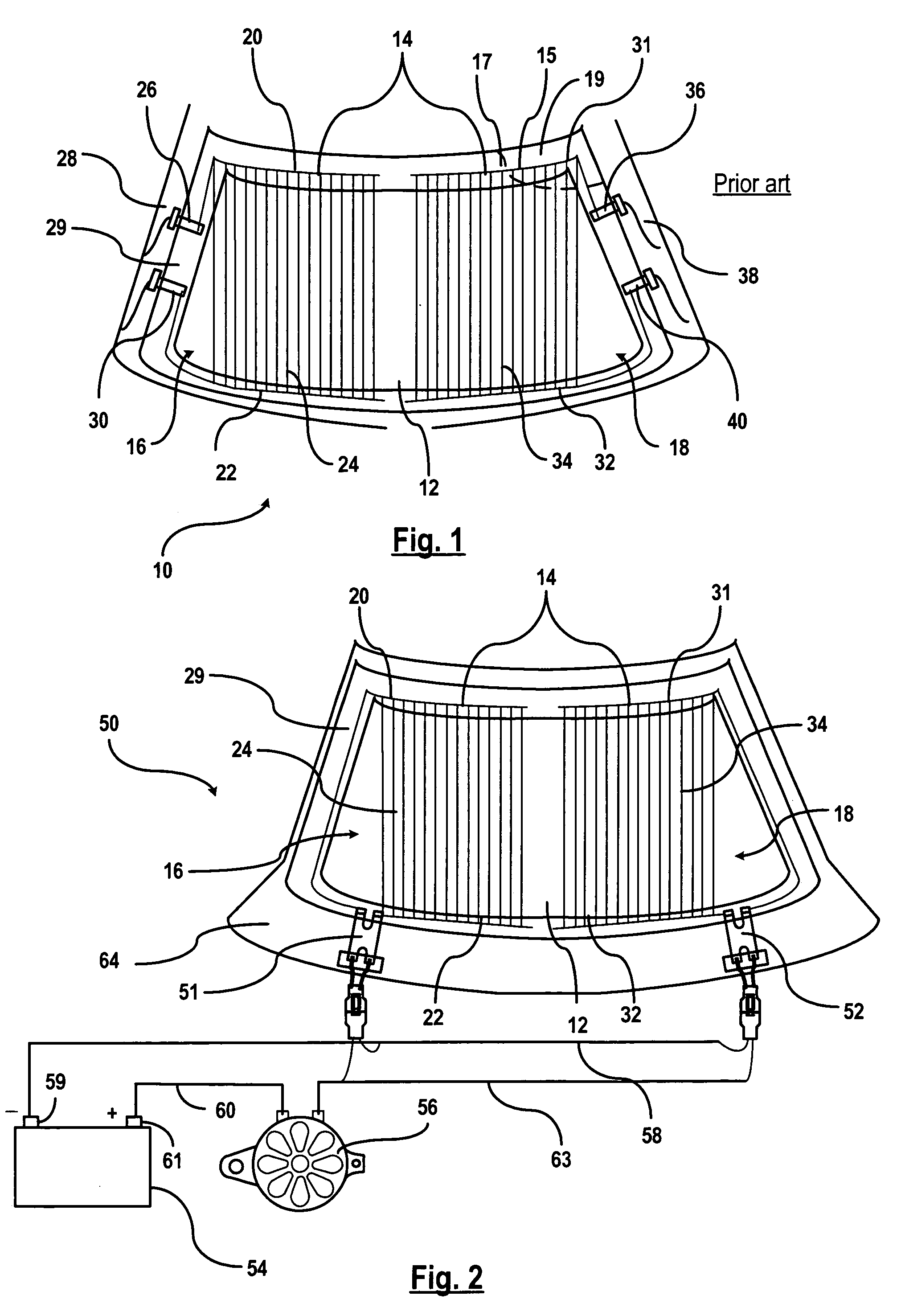
[0021]Referring now to the drawings, there is illustrated in FIG. 1, a typical prior art heated windshield system 10. The heated windshield system typically includes a windshield 12 with an integrated heating windshield circuit 14 embedded within the windshield 12. The heating circuit 14 is embedded in an intermediate layer 15, (e.g., a vinyl layer), between a first transparent pane 17 and a second transparent pane 19 in a glazing operation. Preferably, the two transparent panes are preferably produced from glass. Alternatively, the transparent panes may be produced from a material composition other than glass.

[0022]The heated windshield circuit 14 includes a first heating section 16 and a second heating section 18. The first heating section 16 includes a positive bus bar 20 disposed on an upper-left half portion of the windshield 12 and a negative bus bar 22 disposed on a lower-left half portion of the windshield. A plurality of fine wire elements 24 are connected between the posit...


PUM


Abstract

A power connection apparatus of a vehicle is provided that includes a pair of substantially flat electrical conductor strips each having a first end and a second end. The first ends are adapted to be electrically coupled to integrated heater conductors in an automobile glazing. A film forms a protective coating over an intermediate section of the pair of electrical conductor strips. The film insulates and maintains a spaced relationship between the pair of substantially flat electrical conductors. A pair of wires is electrically coupled to the second ends. A first protective overmold seal is formed over the second ends of the pair of substantially flat electrical conductor strips for sealing the electric coupling of the second ends of electrical conductor strips and the wires.

Description

CROSS-REFERENCE TO RELATED APPLICATIONS[0001]Not ApplicableSTATEMENT REGARDING FEDERALLY SPONSORED RESEARCH OR DEVELOPMENT[0002]Not ApplicableREFERENCE TO A SEQUENCE LISTING, A TABLE, OR A COMPUTER PROGRAM LISTING COMPACT DISC APPENDIX[0003]Not ApplicableBACKGROUND OF THE INVENTION[0004]This invention relates in general to a heated windshield system, and more specifically, to a power connection for providing power to a heated windshield system in a wet area in a vehicle.[0005]Windshield defrost systems typically generate heat, in the form of forced air or conducted heat from window-mounted heating elements to defrost ice build up on a windshield. Heating elements integrated within the windshield offer a uniform and even defrost pattern across the windshield as opposed to forced air. The heating elements include a plurality of fine wires that are embedded within a vinyl intermediate layer of the windshield. The vinyl intermediate layer is sandwiched between two glass panes. Electrica...

Claims


Application Information

Patent Timeline
Patent Type & Authority Patents(United States)
IPC IPC(8): H05B1/02
CPCH05B1/0227H05B2203/013H05B2203/035H05B2203/017H05B2203/016B32B17/10036B32B17/10385H05B3/06
Inventor LOIBL, JOSEPH M.TANKSLEY, MARCUSAGIUS, LARRYHATCHER, ROBERT W.CLEARY, THOMAS M.
Owner CARLEX GLASS AMERICA LLC
Why Eureka
Try Eureka