Multi-mode input impedance matching for smart antennas and associated methods

a smart antenna and input impedance matching technology, applied in the field of wireless communication systems, can solve the problems of adding complexity and cost of phased array antennas, and difficulty in matching input impedances of various modes

Inactive Publication Date: 2007-02-20
INTERDIGITAL TECH CORP
View PDF14 Cites 69 Cited by
  • Summary
  • Abstract
  • Description
  • Claims
  • Application Information

AI Technical Summary

Problems solved by technology

This makes it difficult to match the input impedances of the various modes.
To obtain a reasonable match for required beam shapes and positions, dynamic matching circuits are often used, which further add to the complexity and cost of a phased array antenna.

Method used


Image

  • Multi-mode input impedance matching for smart antennas and associated methods
  • Multi-mode input impedance matching for smart antennas and associated methods
  • Multi-mode input impedance matching for smart antennas and associated methods

Examples


Embodiment Construction

[0028]The present invention will now be described more fully hereinafter with reference to the accompanying drawings, in which preferred embodiments of the invention are shown. This invention may, however, be embodied in many different forms and should not be construed as limited to the embodiments set forth herein. Rather, these embodiments are provided so that this disclosure will be thorough and complete, and will fully convey the scope of the invention to those skilled in the art. Like numbers refer to like elements throughout.

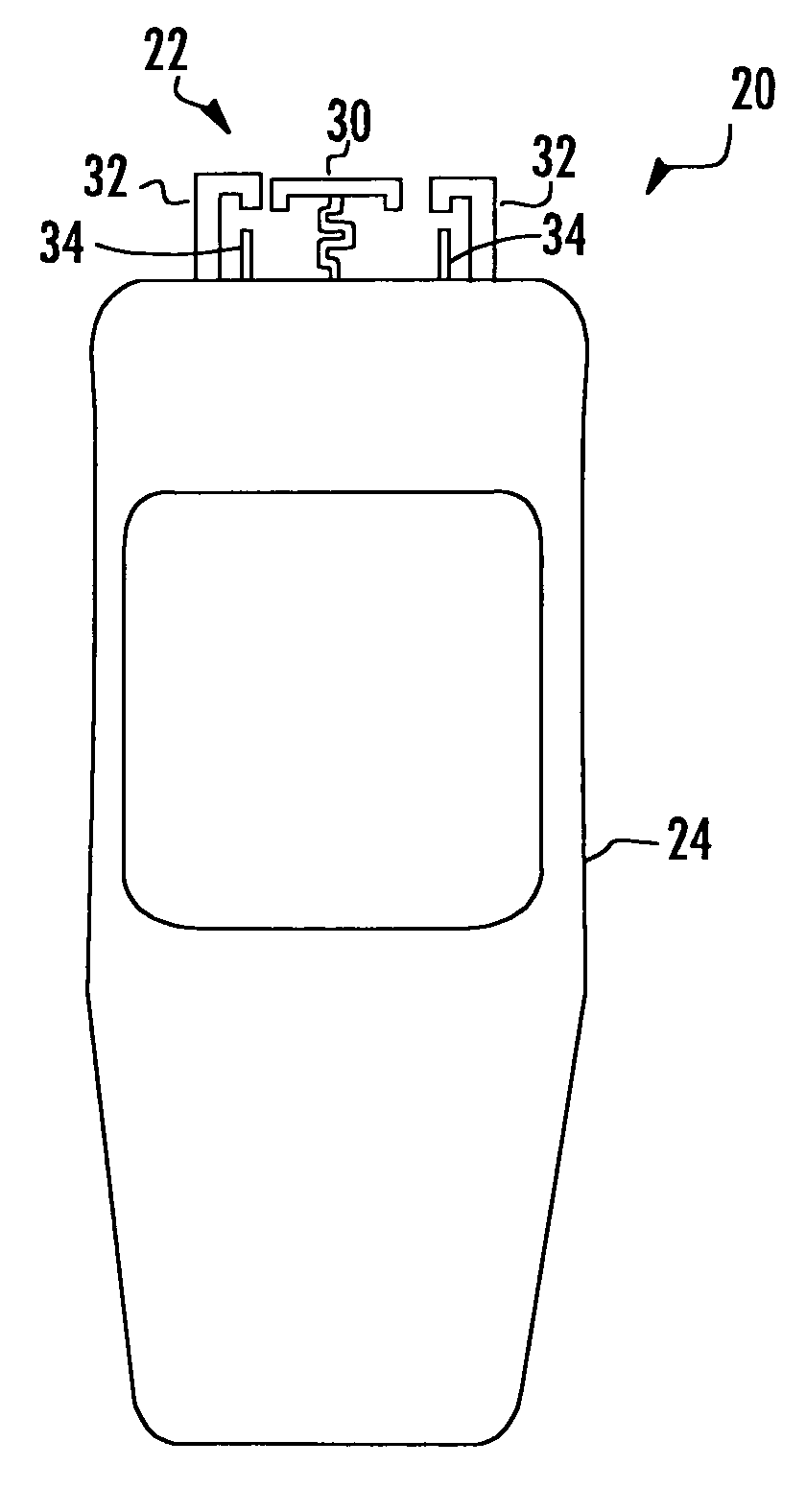
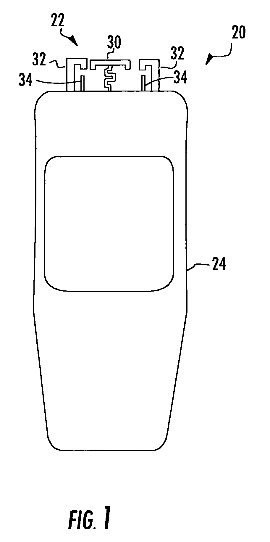
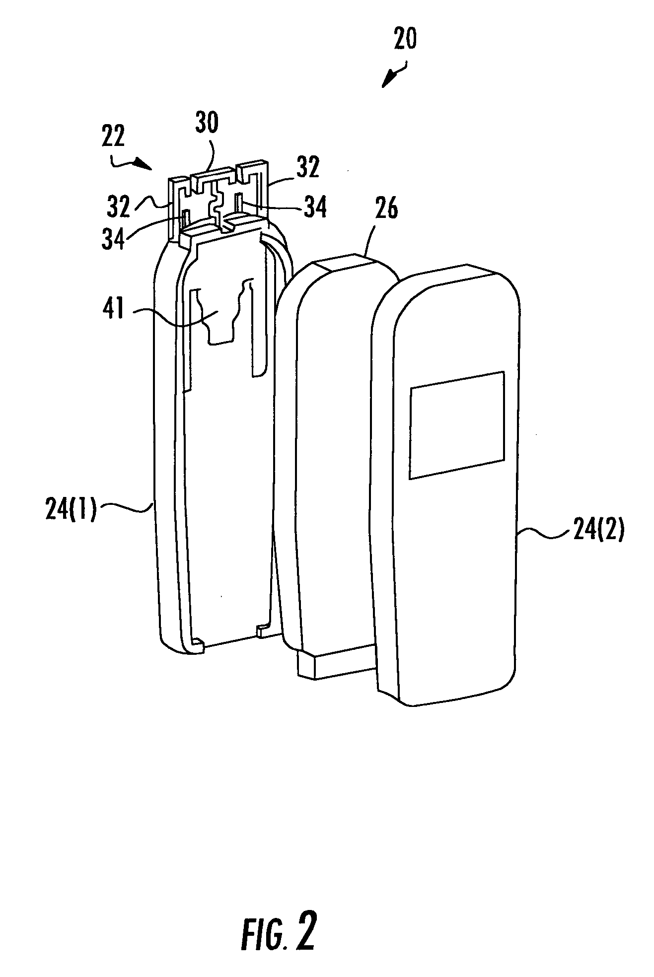
[0029]Referring initially to FIGS. 1–4, the illustrated mobile subscriber unit 20 includes in FIGS. 1 and 2 a smart antenna 22 that protrudes from the housing 24 of the mobile subscriber unit 20, and in FIGS. 3 and 4 a smart antenna that is internal the housing 24. In both cases, the smart antenna 22 includes an active antenna element 30, a plurality of passive antenna elements 32 defining at least one resonant frequency, and a plurality of tuning elements...


PUM


Abstract

A smart antenna includes a ground plane, an active antenna element adjacent the ground plane and having a radio frequency (RF) input associated therewith, and passive antenna elements adjacent the ground plane. Impedance elements are connected to the ground plane and are selectively connectable to the passive antenna elements for antenna beam steering. Tuning elements are adjacent the passive antenna elements for tuning thereof so that an input impedance of the RF input of the active antenna element remains relatively constant during the antenna beam steering.

Description

RELATED APPLICATION[0001]This application claims the benefit of U.S. Provisional Application Ser. No. 60 / 592,318 filed Jul. 29, 2004, the entire contents of which are incorporated herein by reference.FIELD OF THE INVENTION[0002]The present invention relates to the field of wireless communication systems, and more particularly, to a smart antenna operating in different antenna beam modes.BACKGROUND OF THE INVENTION[0003]In wireless communication systems, portable or mobile subscriber units communicate with a centrally located base station within a cell. The wireless communication systems may be a CDMA2000, GSM or WLAN communication system, for example. The subscriber units are provided with wireless data and / or voice services by the system operator and can connect devices such as, for example, laptop computers, personal digital assistants (PDAs), cellular telephones or the like through the base station to a network.[0004]Each subscriber unit is equipped with an antenna. To increase t...

Claims


Application Information

Patent Timeline
Patent Type & Authority Patents(United States)
IPC IPC(8): H01Q1/24H01Q19/00
CPCH01Q1/242H01Q9/36H01Q1/243
Inventor CHIANG, BING A.RICHESON, LEGAL REPRESENTATIVE, DEE M.RICHESON, DECEASED, JOSEPH T.
Owner INTERDIGITAL TECH CORP
Why Eureka
Try Eureka