3D motion picture theatre

Inactive Publication Date: 2007-02-20
COLLENDER ROBERT BRUCE +1
View PDF31 Cites 34 Cited by
  • Summary
  • Abstract
  • Description
  • Claims
  • Application Information

AI Technical Summary

Benefits of technology

[0030]An important objective in the development of our invention was to survey industry for the purpose of finding an optimum concaved mirror technology that would allow a mirror to be constructed 25 feet high or even higher by means of piecing together a matrix of mirror tiles to provide high image quality and low procurement cost. This survey was accomplished. We evaluated 17 technologies and a total of 58 companies. The result led to a molded part with a reflective layer glued to its surface. The mirror-tile is then LAS

Problems solved by technology

The reproduction system suffered from parallax discontinuities, shallow depth of field and the need for multiple projection lamps.
The Russians admitted to the following problems: visual fatigue due to poor left and right eye separation and brightness differences; poor convergence and the appearance of “cardboard” images.
This approach suffers a loss of horizontal detail and is very susceptible to jitter demanding an extremely accurate scan.
The system could not provide a detailed photographic-type image due to a severely limited image writing time constraint.
The images are usually only simple computer graphics figures due to the high scanning speeds required in this process.
The problem with the Stereoptiplexer was that the camera was constrained to look out only one side as it moved horizontally.
McElveen of South Carolina (a

Method used


Image

  • 3D motion picture theatre
  • 3D motion picture theatre
  • 3D motion picture theatre

Examples


Embodiment Construction

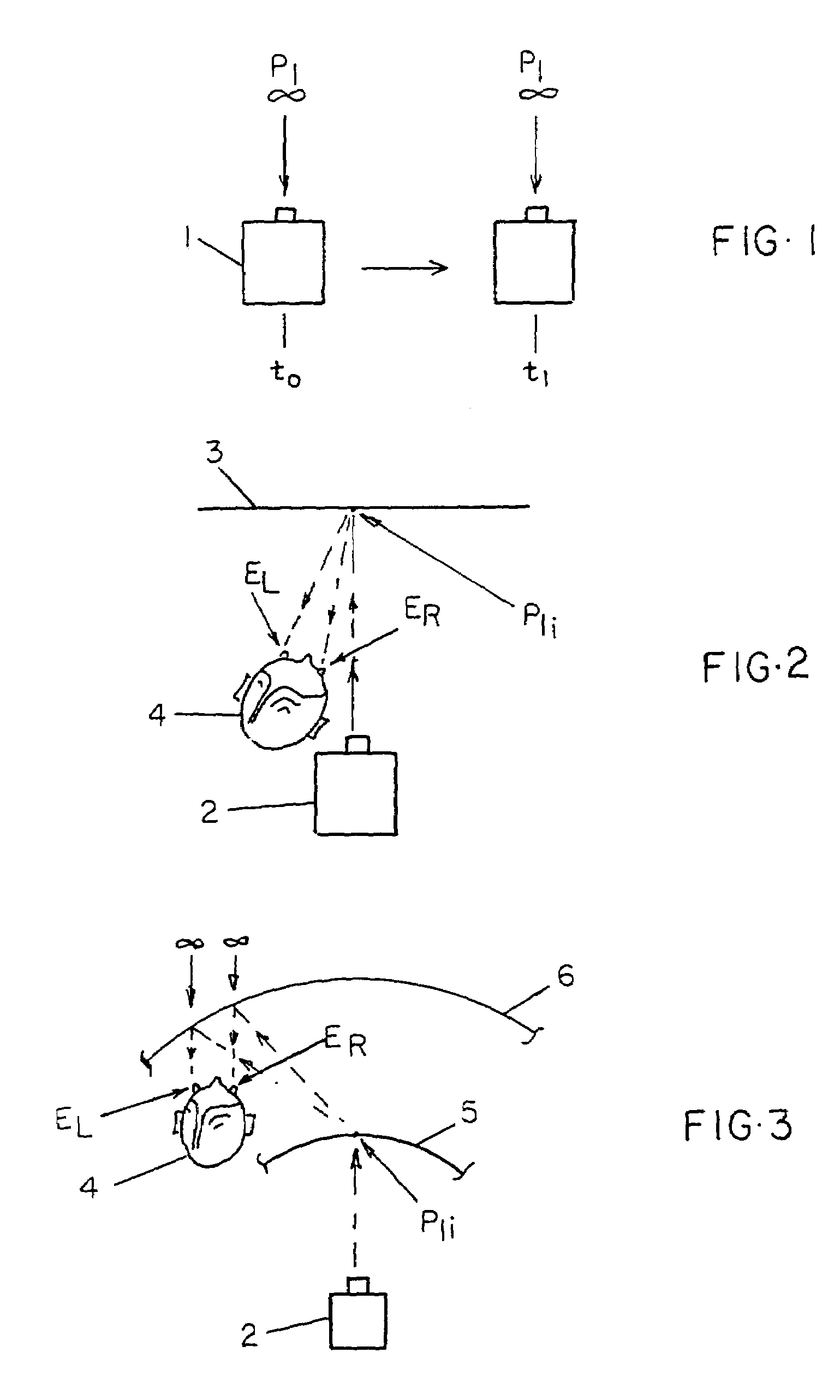
[0077]FIG. 1 shows a movie camera 1 (using film or electronic storage media) moving with a component of horizontal relative motion (between camera and scene) while capturing views of a scene at great distances. P1 represents an object point in the scene at infinity. Camera 1 is shown at two points in time designated by time t0 and time t1 at which times scene point P1 is recorded on the storage media used in camera 1. The views thus captured become images in the successive embodiments of the playback equipment discussed in the remainder of this specification.

[0078]FIG. 2 shows the far image viewing geometry in a plan view of a conventional movie projection system (using film or electronic storage media) where the view captured in FIG. 1 is projected by projector 2 onto reflective screen 3 and image point P1i is viewed by observer 4. Observer 4 sees P1i on screen 3 with left eye EL and right eye ER and the sight lines from eyes to screen image are not parallel as they were for camera...


PUM


Abstract

When any observer receives an image of a scene having the same relative size, shape and location on the retina of each of his two eyes at any instant and the image of the scene has some component of horizontal motion in any direction, the image viewed is three dimensional. If the motion occurs, all scene-object points are spatially located in playback since all of the original ray angles between camera and scene points are reproduced for both eyes by the ray cross-overs at the scene image points. When successive frames are presented, the brain cognizes the motion in linking the frames by persistence of vision. For the brain to perceive an item as moving it must connect these frames, but because of intersecting rays coming from any spatial location in successive frames, the brain cannot connect the frames without also locating the points in space.

Description

CROSS REFERENCES TO RELATED APPLICATIONS[0001]Not ApplicableSTATEMENT REGARDING FEDERALLY SPONSORED RESEARCH OR DEVELOPMENT[0002]Not ApplicableREFERENCE TO A MICROFICHE APPENDIX[0003]Not ApplicableBACKGROUND OF THE INVENTIONLenticular Systems[0004]The history of 3-D technology without glasses that reproduce scenes in motion essentially begins with F and H. Ives in the 1930's with the use of lenticules and film camera / projector arrays. The reproduction system suffered from parallax discontinuities, shallow depth of field and the need for multiple projection lamps.[0005]In the 1940's, Ivanov, in Russia, demonstrated the radial raster stereoscreen constructed of about 3000 long conical lenses imposing very tight tolerances in implementation. Special visors had to be designed to help spectators locate the best view positions. The Russians admitted to the following problems: visual fatigue due to poor left and right eye separation and brightness differences; poor convergence and the appe...

Claims


Application Information

Patent Timeline
IPC IPC(8): G03B21/10G03B21/56G03B25/00G03B35/16H04N13/363
CPCG03B25/00H04N13/0459H04N13/0402G03B35/16H04N13/302H04N13/363
Inventor COLLENDER, ROBERT BRUCECOLLENDER, MICHAEL ARTHUR
Owner COLLENDER ROBERT BRUCE
Why Eureka
Try Eureka