Image coding apparatus and method

a technology of image coding and apparatus, applied in the field of image coding technology, can solve the problems of difficult for novice users to avoid bad effects, low use of high resolution, meaningless pursuit of enhancement of product performance, etc., and achieve the effect of reducing additional computing costs

Inactive Publication Date: 2007-02-20
XACTI CORP
View PDF8 Cites 18 Cited by
  • Summary
  • Abstract
  • Description
  • Claims
  • Application Information

AI Technical Summary

Benefits of technology

[0008]The present invention has been made with a view to the above-mentioned problems, and an object thereof is to provide an image coding technology which can evaluate the quality of an image which may be affected by shooting ...

Problems solved by technology

On the other hand, because of the light weight of the camera body and the high magnification of the optical zoom, it is very difficult for novice users to avoid the bad effects of camera shake during shooting.
In addition, although the resolution of the image is increased very rapidly because of the high density of CCD, such high resolution is not much use when th...

Method used


Image

  • Image coding apparatus and method
  • Image coding apparatus and method
  • Image coding apparatus and method

Examples


embodiment 1

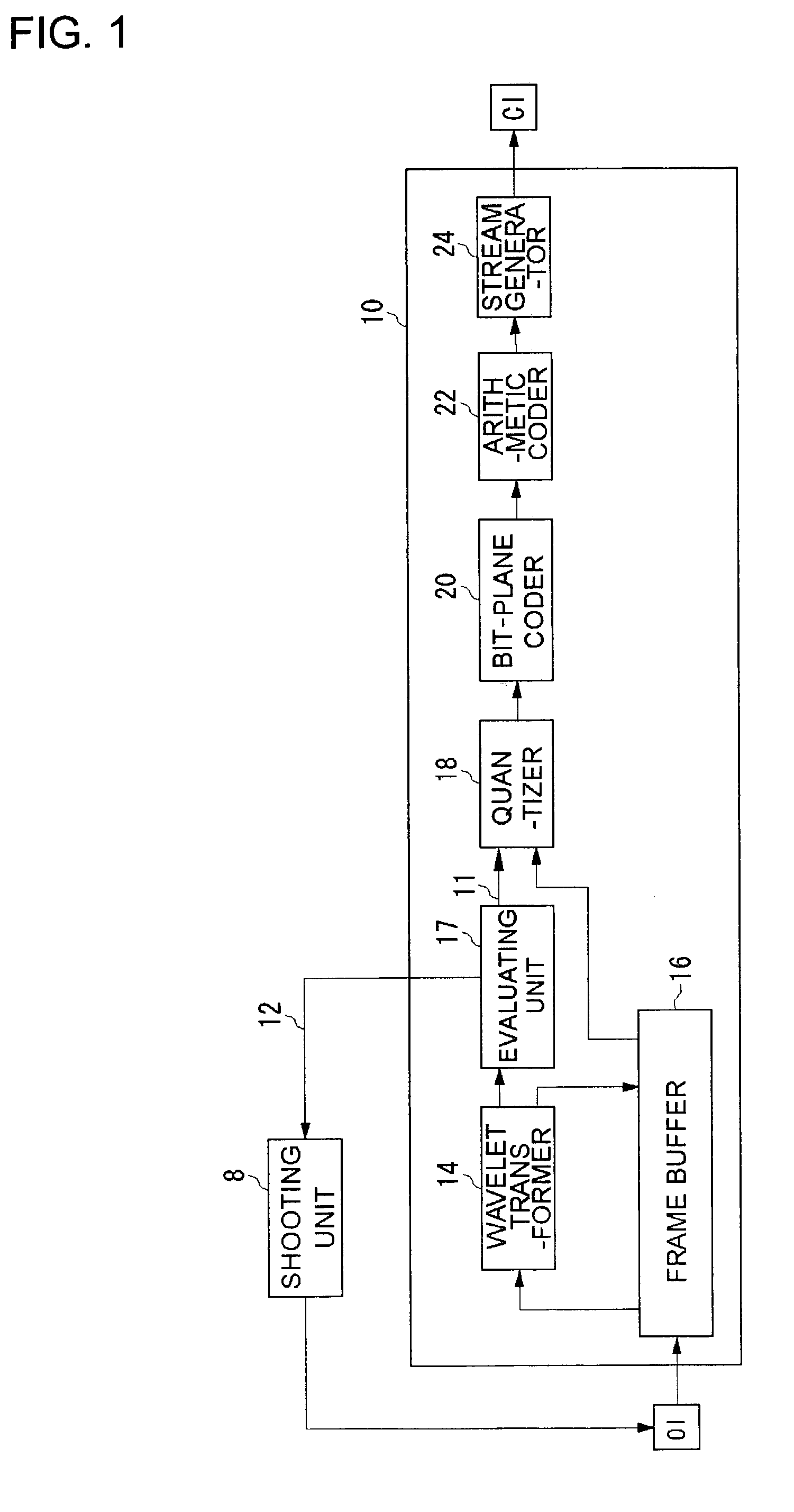
[0026]FIG. 1 shows the configuration of an image coding apparatus 10 according to Embodiment 1. The image coding apparatus 10 codes image data according to JPEG 2000. The specifications of JPEG 2000 are described in the standards document, ISO / IEC 15444-1: JPEG 2000 image coding system, JPEG 2000 Final Committee Draft, Aug. 18, 2000. The image coding apparatus 10 may be a normal computer and comprises a CPU, memory and program modules to code images loaded in the memory. The blocks in FIG. 1 depict functions characteristic of the present embodiment and those skilled in the art understand that the functional blocks can be embodied as hardware only, software only or as a combination of the two.

[0027]The image coding apparatus 10 comprises a wavelet transformer 14, a frame buffer 16, a quantizer 18, a bit-plane coder 20, an arithmetic coder 22 and a stream generator 24. An original image OI is read in the frame buffer 16 when the coding process starts. The image is input directly into ...

embodiment 2

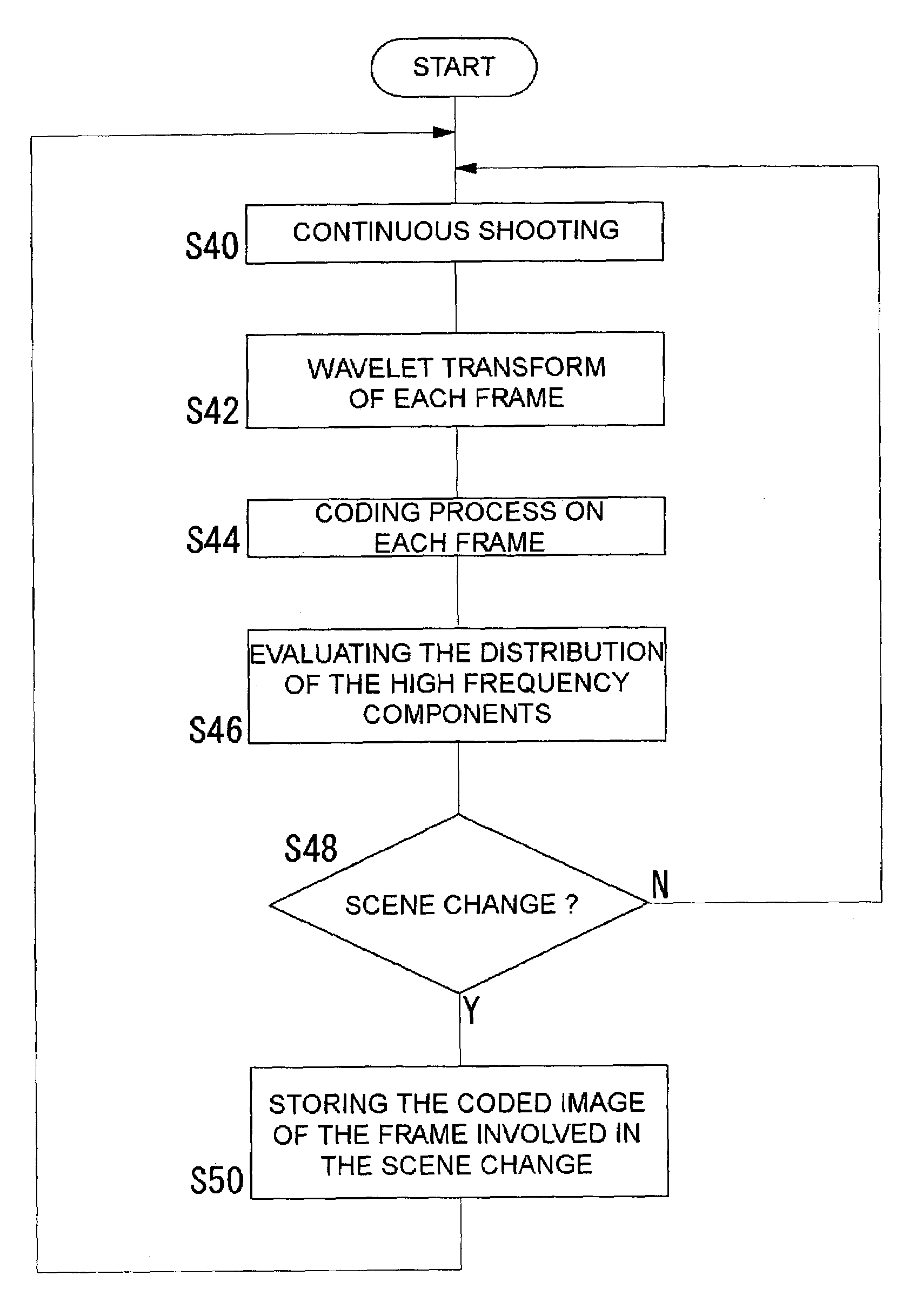
[0037]FIG. 5 shows the configuration of an image coding apparatus 10 according to Embodiment 2. In Embodiment 2, the original images OI1 to OIn continuously shot by the shooting unit 8 are input to the frame buffer 16. This continuous shooting may be performed for a relatively short period as a sequential shooting by a digital camera or may be performed for a long period as in a security camera. The manner in which the structure and behavior of this embodiment differs from those of Embodiment 1 are now explained below.

[0038]Each of the original images OI1 to OIn stored in the frame buffer 16 is transformed by the wavelet transformer 14. Each of the transformed images is processed by the quantizer 18, the bit-plane coder 20, the arithmetic coder 22, and the stream generator 24. Coded image data CI1 to CIn corresponding to the original images OI1 to OIn are finally generated by the stream generator 24 and stored in the memory 25.

[0039]The evaluating unit 17, as in Embodiment 1, evalua...


PUM


Abstract

An original image shot by a shooting unit is read in a frame buffer and transformed by a wavelet transformer. An evaluating unit monitors the coefficients of the HL, LH, HH sub-bands generated by the wavelet transformer and checks the number of the high frequency components in the original image. If there are sufficient high frequency components, the quality of the original image is judged to be good, and if not, the image quality is judged not to be good because of camera shake or the like. The evaluating unit sends a coding indication signal to a quantizer if the image quality is good. Thereby the wavelet transformed image is coded. If the image quality is not good, the evaluating unit sends a re-shooting indication signal to the shooting unit.

Description

BACKGROUND OF THE INVENTION[0001]1. Field of the Invention[0002]This invention relates to an image coding technology, and it particularly relates to method and apparatus for evaluating the quality of an image during the coding process.[0003]2. Description of the Related Art[0004]During the 1990's in particular, the widespread use of PCs (personal computers) and other information equipment, the popularization of digital cameras, color printers and so forth and the explosive increase in the use of the Internet accounted for a deep infiltration of the culture of digital images into the everyday life of ordinary people. Under these circumstances, coding and compression technologies such as JPEG (Joint Photographic Experts Group) for static images and MPEG (Moving Picture Experts Group) for moving images, have been standardized so as to improve the facility of distribution and reproduction of images through recording media such as CD-ROMs, and transmission media such as networks and broa...

Claims


Application Information

Patent Timeline
IPC IPC(8): G06K9/46G06T9/00H03M7/30H04N1/41H04N5/232H04N19/423H04N19/60H04N19/635H04N19/91
CPCH04N5/232H04N19/63H04N19/179H04N19/14H04N19/10H04N23/60
Inventor OKADA, SHIGEYUKIYAMAUCHI, HIDEKI
Owner XACTI CORP
Why Eureka
Try Eureka