Cardiac restraint with electrode attachment sites

a technology of electrode attachment and cardiac restraint, which is applied in the field of heart failure treatment, can solve the problems of inability to adapt the cardiac resynchronization device to the needs of the patient, and the electrode placement is less than ideal, and achieves the effect of efficient electrical pacing stimulation of the chamber, convenient and convenient electrode placement, and convenient patient customization

Inactive Publication Date: 2007-02-20
MEDTRONIC INC
View PDF50 Cites 31 Cited by
  • Summary
  • Abstract
  • Description
  • Claims
  • Application Information

AI Technical Summary

Benefits of technology

[0013]The needs of the patient may depend upon factors such as his past medical history and his anatomy. In conventional cardiac resynchronization, sensing and pacing electrodes may by implanted endocardially, that is, within the chambers of the heart, or endovenously, that is, in the cardiac veins. In some patients, such electrode placements are less than ideally effective due to conditions such as myocardial scar tissue created by earlier myocardial infarctions. For such patients, the electrodes may be more effective when placed epicardially, that is, on the surface of the heart. One object of the invention is to make epicardial electrode placement easier and more easily customized to the patient.
[0014]Another object of the invention is to allow for more electrode placements than may be possible with endocardial or endovenous implantation. In some patients, cardiac resynchronization may be performed more efficiently when several electrodes are disposed proximate to a single cardiac chamber. When more electrodes are disposed around a chamber, the conductive pathways activating the chamber can be mapped, and strategies for efficient electrical pacing stimulation of the chamber can be developed.

Problems solved by technology

These problems include, for example, an inability to adapt a cardiac resynchronization device to the needs of the patient.
In some patients, such electrode placements are less than ideally effective due to conditions such as myocardial scar tissue created by earlier myocardial infarctions.

Method used


Image

  • Cardiac restraint with electrode attachment sites
  • Cardiac restraint with electrode attachment sites
  • Cardiac restraint with electrode attachment sites

Examples


Embodiment Construction

[0031]In the following detailed description of the preferred embodiments, reference is made to the accompanying drawings that form a part hereof, and in which are shown by way of illustration specific embodiments in which the invention may be practiced. It is to be understood that other embodiments may be utilized and structural or logical changes may be made without departing from the scope of the present invention. The following detailed description, therefore, is not to be taken in a limiting sense, and the scope of the present invention is defined by the appended claims.

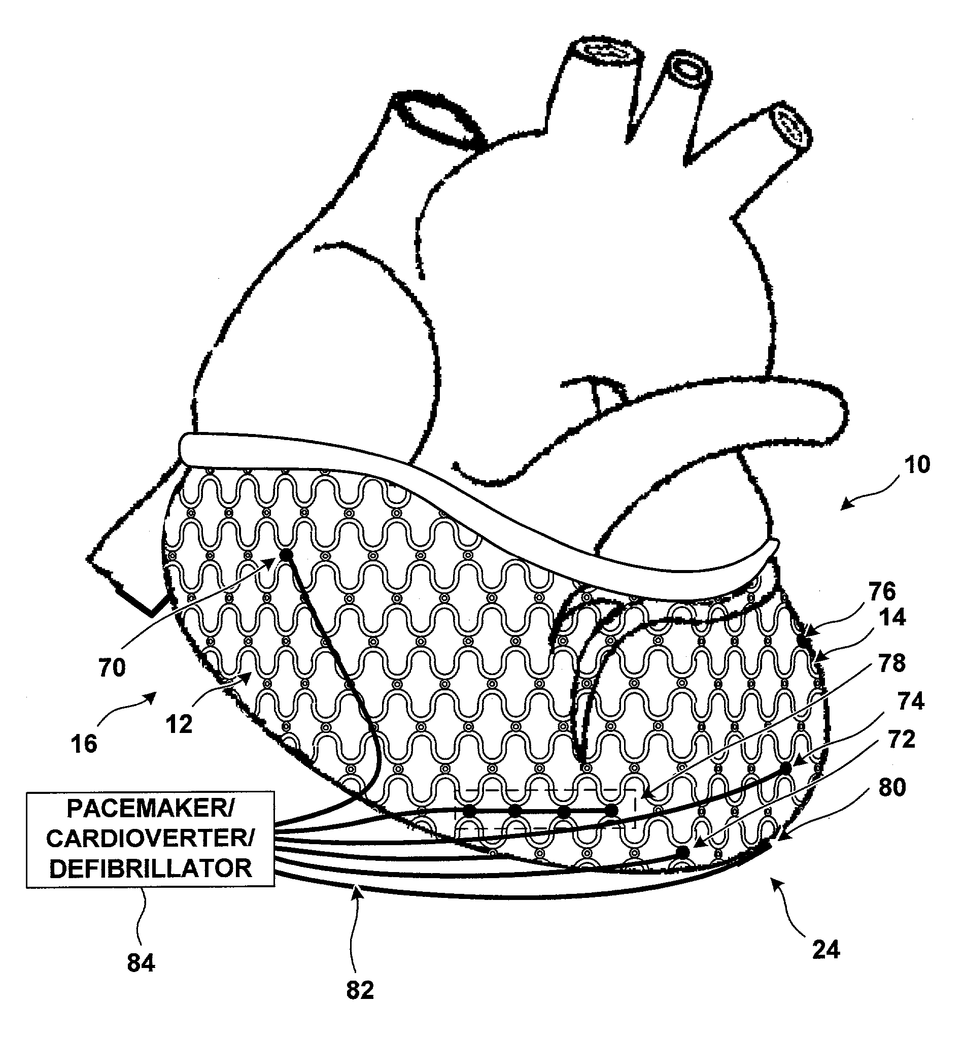
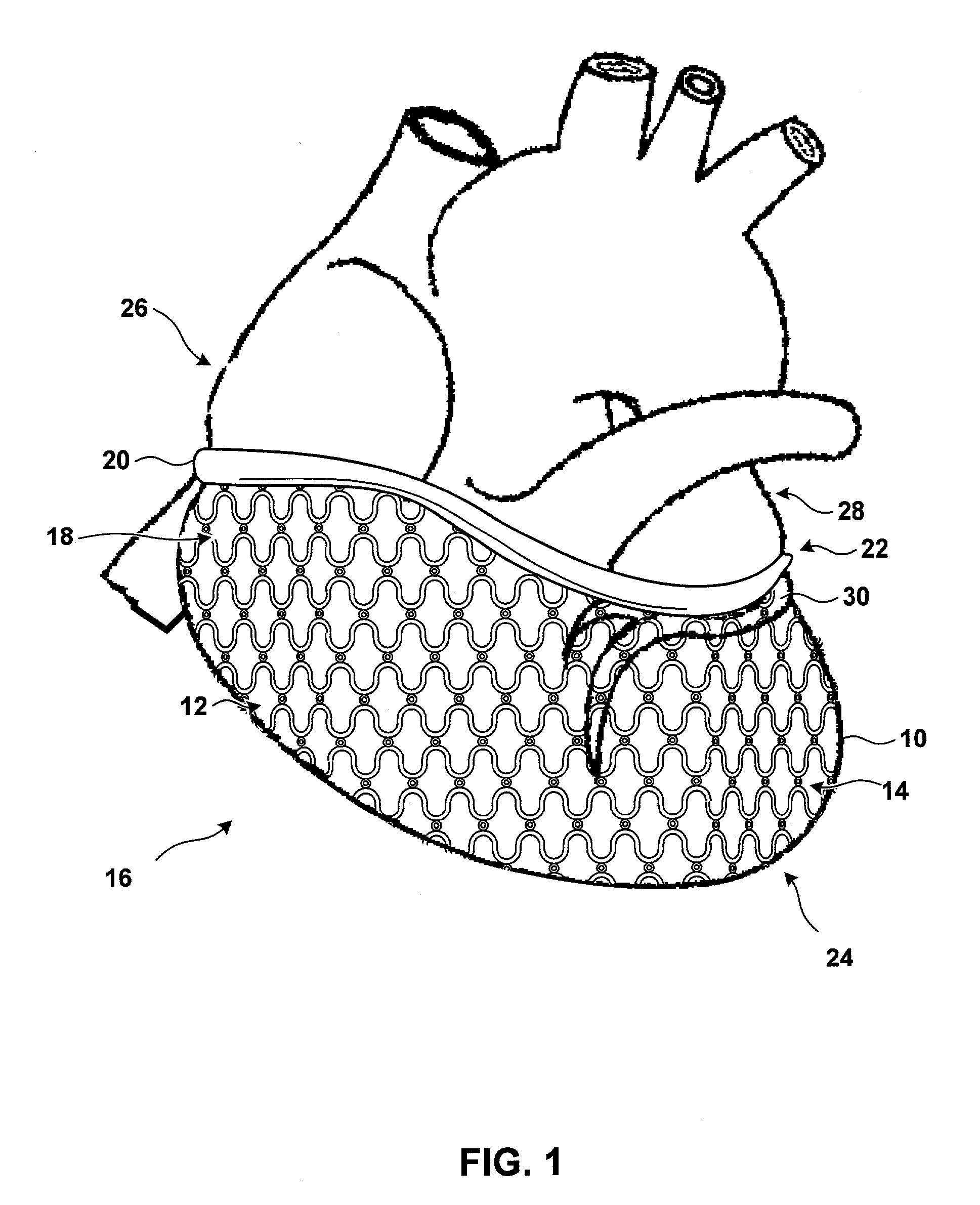
[0032]FIG. 1 shows a human heart 10. Right ventricle 12 and left ventricle 14 of heart 10 are jacketed by a harness 16. Harness 16 includes a mesh-like restraint 18 and a circumferential attachment member 20. Circumferential attachment member 20 secures harness 16 proximate to the base 22 of heart 10.

[0033]Harness 16 may be placed around heart 10 during open-heart surgery. The patient is typically placed in the s...


PUM


Abstract

The invention is directed to techniques for electrode placement around a heart. A harness having one or more attachment sites may be secured around the heart, and electrodes may be secured at the attachment sites as desired by the physician for the patient. The electrodes may be, for example, pacing and sensing electrodes, defibrillation electrodes, or any combination thereof. The harness holds the electrodes in place and also impedes the progress of ventricular dilation. The electrodes attached to the harness may be used for any of several purposes, such as cardiac resynchronization, selective defibrillation, measurement of impedance, pacing and cardioversion.

Description

FIELD OF THE INVENTION[0001]The invention relates to treatment of heart failure, and more particularly to systems that use electrodes for functions such as sensing, pacing or defibrillation.BACKGROUND[0002]Many patients that suffer from congestive heart failure (CHF) develop a wide QRS complex resulting from a delayed activation of one of the ventricles in the heart, and inter- and / or intraventricular electro-mechanical dysynchrony. This ventricular “dysynchrony” may be caused by dilation of the heart, which disrupts the conductive pathways and interferes with depolarization sequences. Ventricular dysynchrony may worsen heart failure symptoms.[0003]In a classic case of ventricular dysynchrony, the patient's right ventricle activates first, and the left ventricle activates at a later time. The patient often experiences a reduction in cardiac output because the ventricles begin contraction at significantly different times. The timing imbalance may also cause the patient to experience ...

Claims


Application Information

Patent Timeline
Patent Type & Authority Patents(United States)
IPC IPC(8): A61N1/05
CPCA61N1/0597
Inventor STRUBLE, CHESTERGRANDJEAN, PIERRE A.ZEIJLEMAKER, VOLKERT A.SMITS, KAREL F. A. A.
Owner MEDTRONIC INC
Why Eureka
Try Eureka