
System and method for testing, simulating, and controlling computer software and hardware

a technology of applied in the field of system and method for testing, simulation, and controlling computer software and hardware, can solve the problems of inefficient, time-consuming, and laborious test methods, and achieve the effect of enhancing test procedures

Inactive Publication Date: 2007-02-20
MICROSOFT TECH LICENSING LLC
View PDF2 Cites 48 Cited by
  • Summary
  • Abstract
  • Description
  • Claims
  • Application Information

AI Technical Summary

Benefits of technology

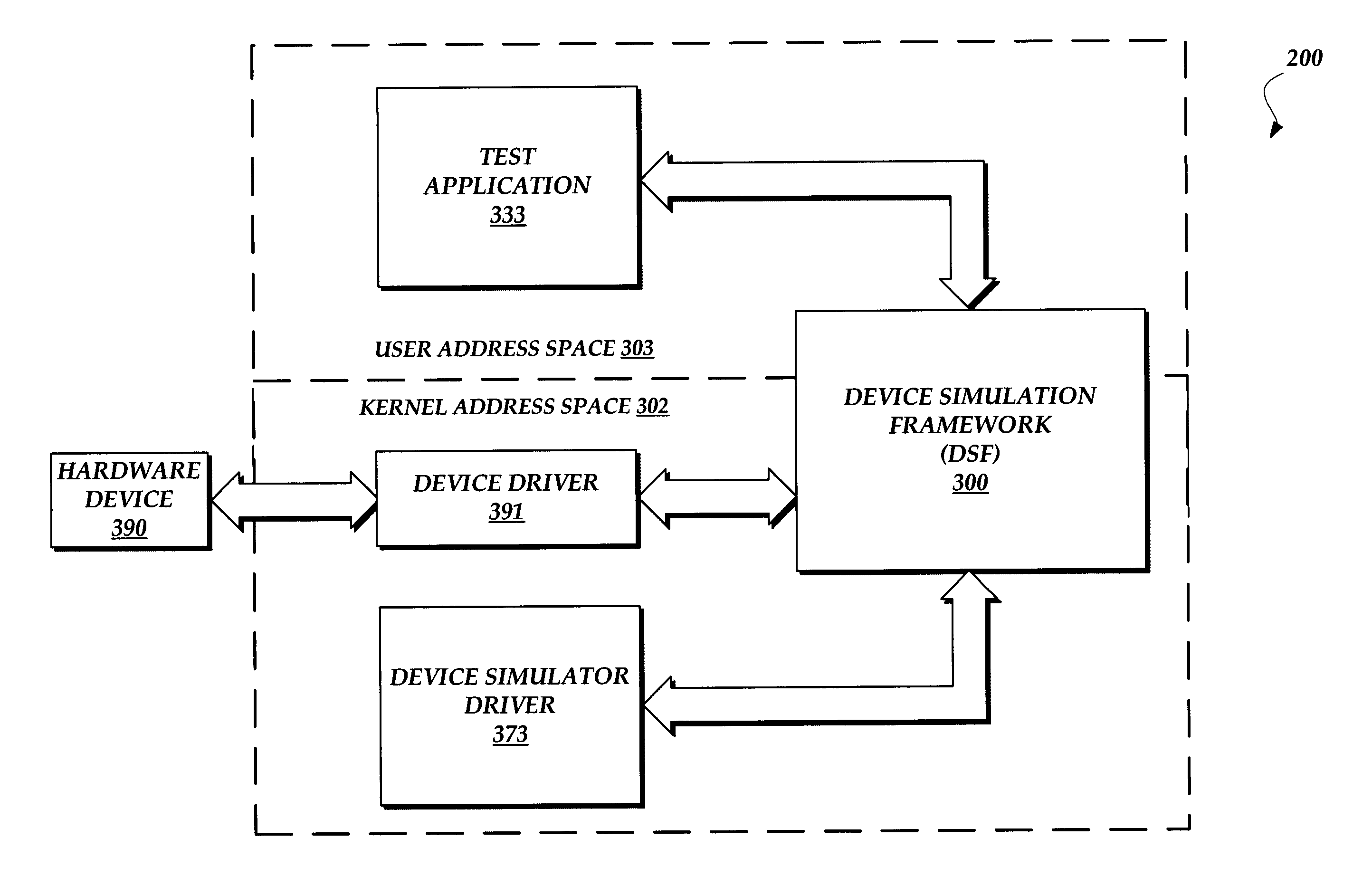
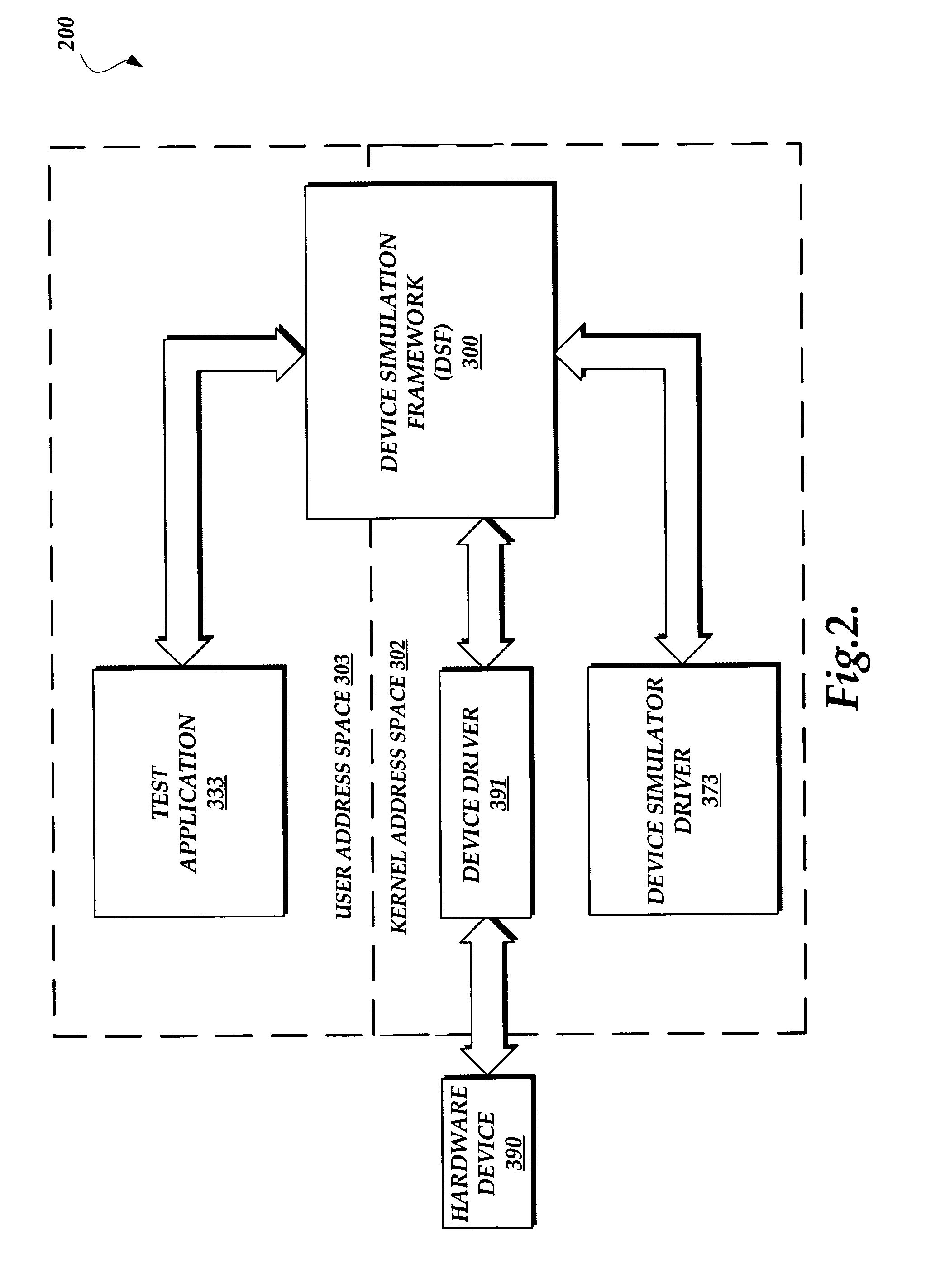
The present invention is a system and method that improve the testing of hardware devices, device drivers, and software applications that communicate with device drivers. It provides a communication channel that allows an application operating in user address space of an operating system to communicate with a device driver or device simulator driver operating in kernel address space of the operating system. This allows for extensive automation of device and device driver testing without tester intervention. The system and method also provide a framework for redirecting hardware interaction and enhancing test procedures. Overall, the invention improves the efficiency and accuracy of testing hardware and software components.

Problems solved by technology

Computing environments for testing hardware devices, hardware drivers, and software applications that communicate with hardware drivers introduce many drawbacks because hardware devices and device drivers must be physically connected to and / or installed in a computer product prior to the execution of the test procedures.
Thus, conventional test methods include an inefficient, time-intensive step that requires a person to physically install or connect a hardware device and manually load one or more software drivers for the hardware device.
Among many other disadvantages, testing methods involving the manual installation of software and hardware components often encounter problems caused by human error.
Such test environments are further hampered by the cumbersome task of coordinating test procedures between many human testers assigned to simultaneously test large quantities of computer products at one time.
The aforementioned drawbacks are exacerbated by the fact that conventional test environments require a tester to manage large inventories of hardware devices.
Given the voluminous number of makes and models of each type of hardware device, testing tasks are further burdened by the fact that existing test methods require that a human tester manage the logistics of acquiring each hardware device and then perform tests on each make and model.
Existing test procedures are further burdened by the fact that the tester is required to maintain complex logs of test results.
These manual tasks introduce many additional problems caused by human error.
Although some existing automation tools, such as a hard-coded device simulator, improve certain aspects of software test procedures, such automation tools present other drawbacks.
One drawback of existing device simulators stems from the fact that they are hard-coded, requiring each device simulator to be redesigned and rebuilt each time the functional characteristics of the tested device are modified.
Because of this drawback in most computing environments, hard-coded device simulators do not offer a flexible and cost-efficient hardware device testing solution.
Although scripts are useful in testing certain user-level applications, test scripts cannot be readily configured to communicate with hardware drivers because they cannot directly communicate with software components located in the kernel address space of an operating system.
Thus, the prior art test automation scripts and programs normally used for applications that operate in a user address space of an operating system cannot be readily applied to tests involving hardware devices and device drivers.

Method used


Image

  • System and method for testing, simulating, and controlling computer software and hardware
  • System and method for testing, simulating, and controlling computer software and hardware
  • System and method for testing, simulating, and controlling computer software and hardware

Examples


Embodiment Construction

[0026]For purposes of illustrating the present invention, a detailed description of a number of software implemented methods is provided. In addition to providing a detailed description of the functionality of each method, the following description also refers to a class name and a method name of defined software method specifications, which are further defined in the appendices of this application. The following description also refers to specific software-coded methods that are known in the art and publicly available at a number of programming resources—for example, the Microsoft® Developer Network database which is well known to those skilled in the art. Although the following description of an exemplary embodiment of the invention refers to Windows® specific implementations, the invention should not be construed as limited to the Windows® operating system. The description includes details sufficient for one of ordinary skill in the art to be able to implement the invention on ot...


PUM


Abstract

A system and method for providing an extensibility model to create device simulators. The system and method provide a generalized framework for the simulation of hardware devices controlled by software drivers with user and kernel mode programmability. The present invention also provides a framework that facilitates communication between applications operating user address space of an operating system and device drivers and device simulators operating in kernel mode address space of the operating system. In one embodiment, a framework provides a bi-directional communication channel that allows a test application in user address space of an operating system to communicate with a computer component operating in kernel address space of the operating system.

Description

FIELD OF THE INVENTION[0001]The present invention relates to computer hardware and software and, more particularly, to systems and methods for testing, simulating, and controlling hardware devices and software components.BACKGROUND OF THE INVENTION[0002]In recent years, there has been a tremendous growth in the use of computer products, i.e., products that contain a data processor, such as desktop and laptop computers, personal data assistants (PDAs), computerized mobile phones, and the like. The increased use of computer products has placed additional production demands on existing manufacturing and testing capabilities. The increased production demands, along with a longstanding interest to continually improve the quality of manufactured computer products, have intensified a continuing need to improve the efficiency of test procedures. As described below, the need for improved efficiency is especially acute for quality test procedures involving computer hardware devices, such as a...

Claims


Application Information

Patent Timeline
Patent Type & Authority Patents(United States)
IPC IPC(8): G06F17/50G06F11/00G06F13/00G06F15/00G06F3/00G06F9/44G06F9/46H03M13/00
CPCG06F11/2273G06F9/4411G06F9/443G06F9/449
Inventor SHIER, PETERMAMTANI, VINOD
Owner MICROSOFT TECH LICENSING LLC
Learn More