Method and system for emergency evacuation of building occupants and a method for modernization of an existing building with said system

a technology for emergency evacuation and building occupants, applied in the direction of instruments, elevators, audio advertising, etc., can solve the problems of unsafe environment, inability to deal with the ongoing use of elevators, and inability to consider elevators as reliable means of egress, etc., to achieve the effect of superior efficiency and rapidity

Active Publication Date: 2007-02-27
INVENTIO AG
View PDF13 Cites 95 Cited by
  • Summary
  • Abstract
  • Description
  • Claims
  • Application Information

AI Technical Summary

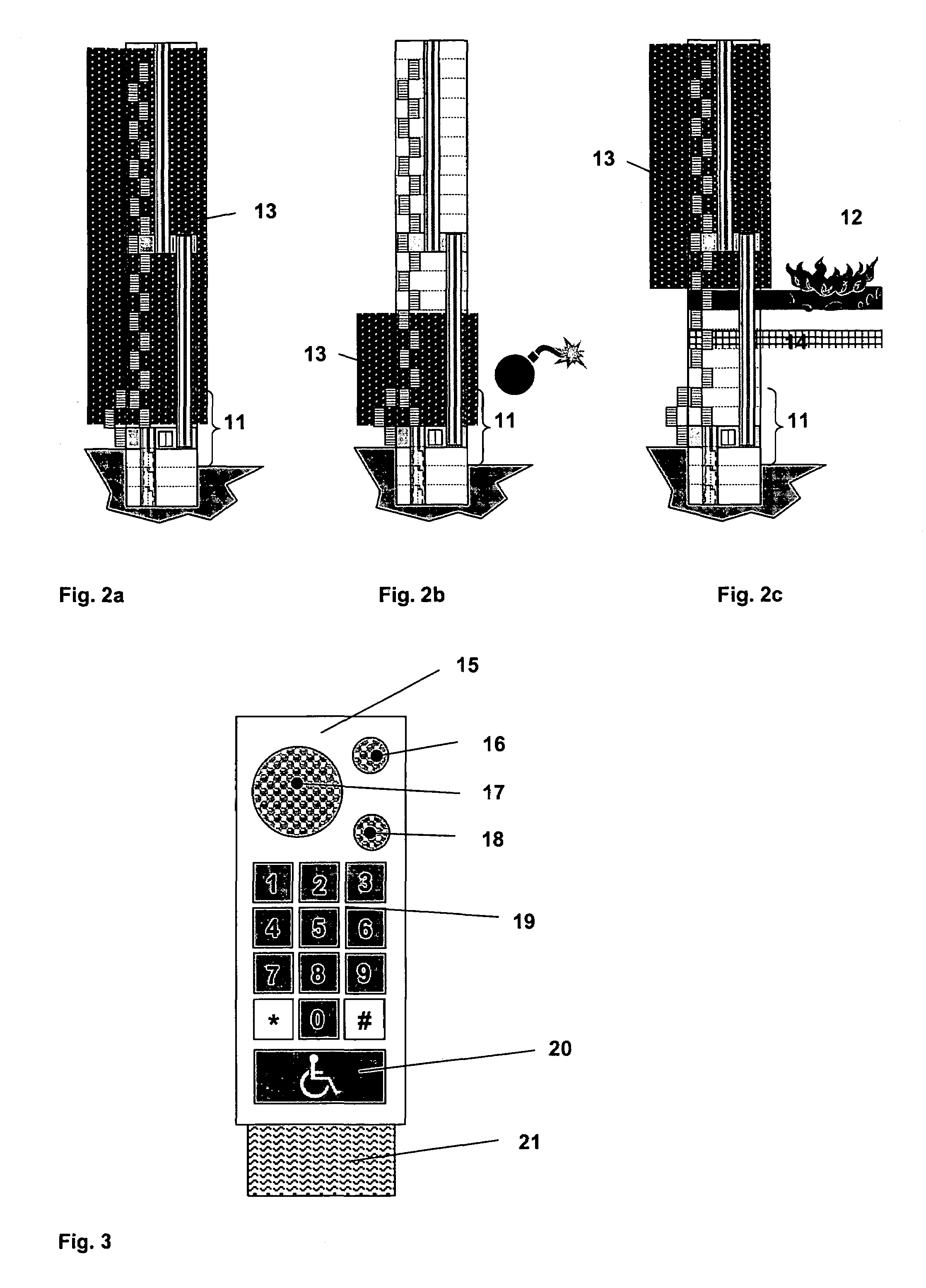
Benefits of technology

[0009]It is an advantage of the present invention, that it allows in the first embodiment a precise determination of the number of building occupants and that in the second embodiment it uses an estimated determination of the number of building occupants. Preferably, according to the first embodiment, the first means may be a car load detector and / or destination call identification device wherein the entry location of a call is the starting floor, the call is fed into the control unit and allocated to an elevator, and the elevator user is then transported from the starting floor to the destination floor. The number of elevator users transported to destination floors is counted and stored in a memory. Of course, first means destination identification devices or car load detectors can also be installed at the entrances of stairways and escalators, allowing the control unit to also count and identify people not acceding to the building with the elevators. By assuming that all transportation within the building occurs by destination call identification, the control unit always knows exactly the number of building occupants present at each floor.
[0010]The destination call may be entered at a landing fixture or read from an identification medium, like a tag or card. This last option exhibits the advantage that personal identification codes can be stored in the identification card and transmitted to the control unit at the moment of the elevator call. In this way the control unit can detect and control the position in the building of disabled persons, VIP, children and any other category of people and can use this information to calculate and prioritize the evacuation procedures.
[0011]In an advantageous embodiment of the invention, the control unit can detect which kind of emergency has occurred, for example fire, bomb scare, terrorist attack, flood, earthquake, hurricane. It is an advantage of this embodiment of the invention that it allows to link the number of building occupants with the emergency condition detected in the building. It is therefore possible, to define an evacuation zone and a designated floor in accordance with the number of building occupants in each floor. Because the number of building occupants within the evacuation zone is known, the most suitable designated floor and the fastest emergency evacuation procedure using stairways and the elevator can be defined.
[0012]It is another advantage of the present invention, that it allows in the second embodiment avoids the problems originating from a situation of panic in a multitude of frightened people. In this case, preferably all elevator cars open their doors synchronously at a floor in the evacuation zone, allowing the largest number of people to enter into the elevators at the same time. This procedure avoids the well-known inconvenience occurring in panic situations, that people crowd together into an elevator car, preventing the elevator doors from closing and preventing the elevator car from leaving the floor and rescue the people. If one floor at a time is evacuated in this way, people waiting in the evacuation zone can be rescued with an efficiency and rapidity superior to other evacuation procedures.

Problems solved by technology

Traditionally, an elevator is not considered as a reliable means of egress during a building fire.
EN81-73, however, does not deal with the ongoing use of the elevator after a fire has been detected and will be fought.
Especially in buildings with more than six floors, the fire department personnel must use also the stairway to advance on the fire and will be hindered by people, who are escaping by using the stairway.
In particular, the unsafe environment concerns the hoistway, the landing doors and the stairway.
One significant reason that an elevator may not be used for emergency egress during a building fire is the danger presented by smoke.
Smoke also contains toxic gases and combustion products, which create an untenable environment for people and expose them to increased risk.
Finally, EN81-73 does not consider the chaotic environment and irrational psychological reactions of the building occupants, which increases the time required to evacuate the building and results in panic and injury to themselves and others.
U.S. Pat. No. 6,000,505 discloses a system characterized by the use of smoke detectors, which is limited to the case of fire and does not consider other emergency situations requiring an evacuation with elevators, such as bomb scare, terrorist attack, hurricane, flood, or an earthquake.
Furthermore, this system is automatic, but not intelligent and cannot take into account how many people are waiting to be saved on a determined floor and whether among these people some are handicapped.
Moreover, this system is not flexible and not able to calculate special and faster strategies to evacuate all people in a building with the elevator.
Because an elevator is conceptualized as unsafe during emergencies, the use of an elevator during an emergency is likely to be perceived as high risk.
Moreover, a sign placard located within the elevator car and at each elevator lobby, such as shown by FIG. 8 of U.S. Pat. No. 6,000,505 is clearly insufficient to guide panicked people into an elevator during an emergency situation.

Method used


Image

  • Method and system for emergency evacuation of building occupants and a method for modernization of an existing building with said system
  • Method and system for emergency evacuation of building occupants and a method for modernization of an existing building with said system
  • Method and system for emergency evacuation of building occupants and a method for modernization of an existing building with said system

Examples


Embodiment Construction

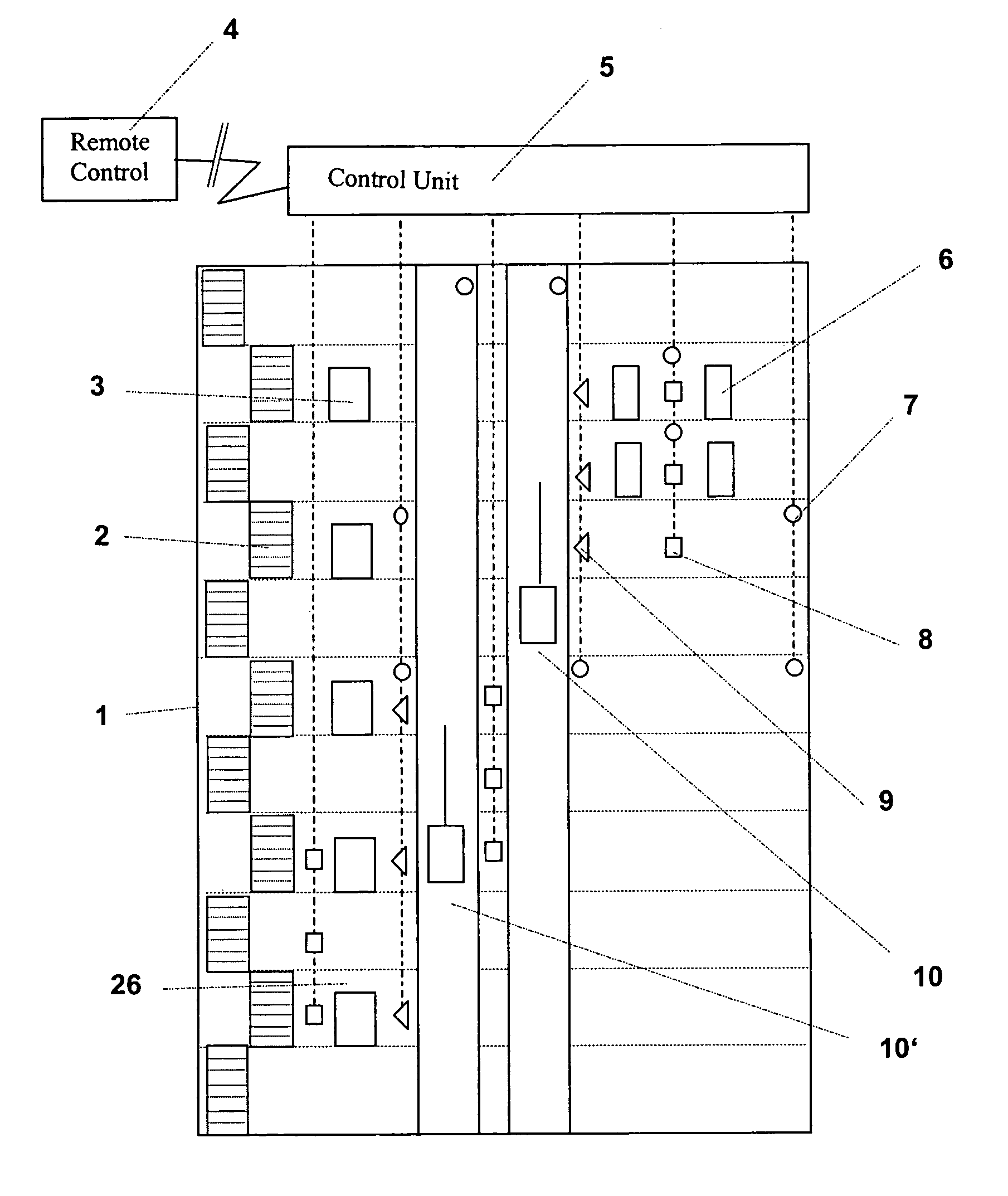
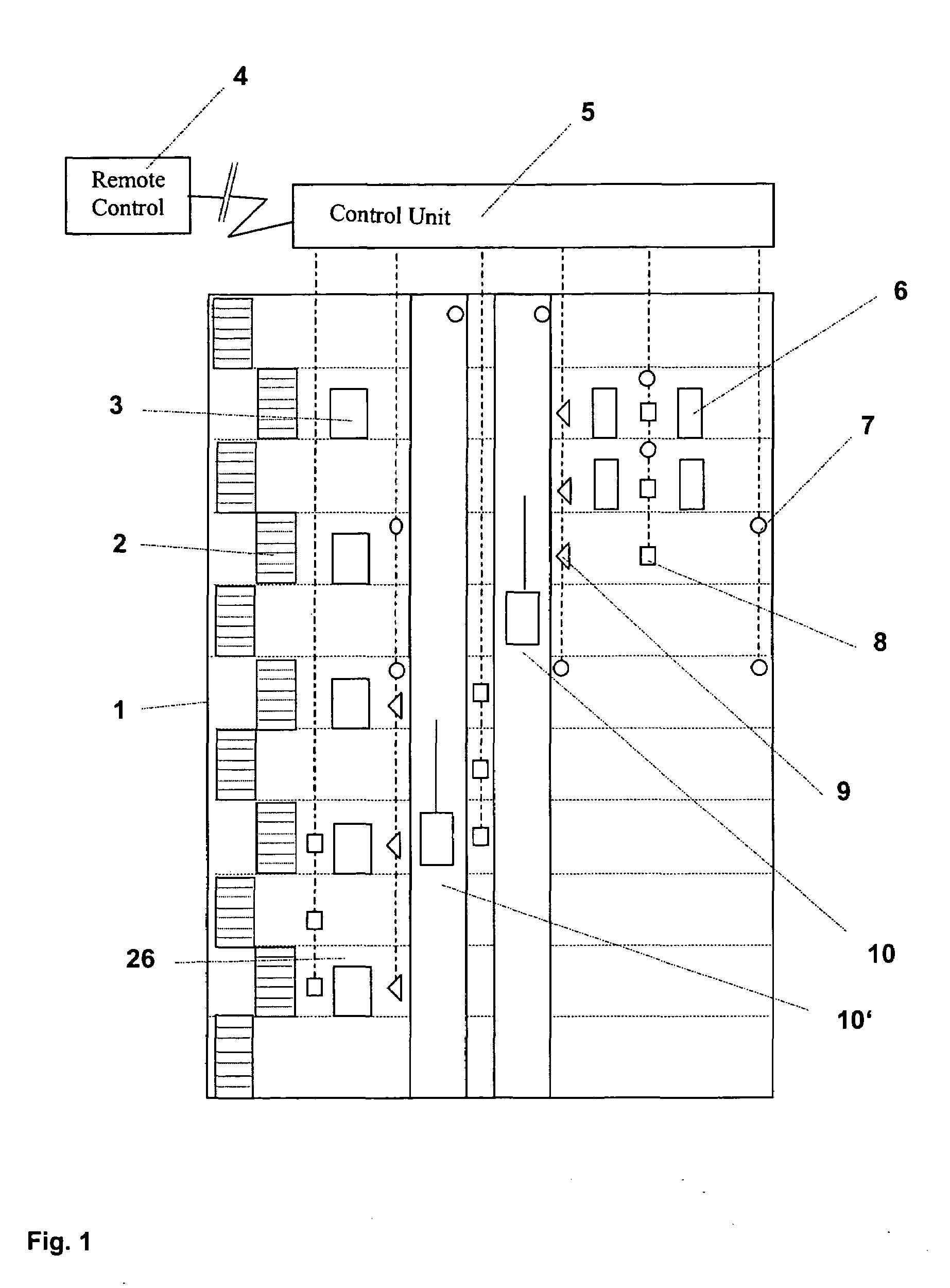
[0020]FIG. 1 depicts a multi-story building 1 with a preferred embodiment of a system according to the invention. The building users and occupants have access and egress to the building either by the stairways 2 or by the elevators 10, 10′. The elevators 10, 10′ may be a single one, one of an electrically interconnected group of elevators, or the cars may be multi-deck. The elevator car is positionable at selected landings 26 of the floors. Access from and to the elevator at the landing occurs via doors 3. The landing is a building zone being e.g. the ground floor lobby, a sky-lobby or a part of a floor passage. The elevator hoistway doors 3 give access to the different floors of the building, in which building doors 6 serve to connect different rooms and spaces. The elevators 10, 10′ are controlled and driven by a control unit 5, which can consist, for instance, in a computer or a group of computers connected with the elevator drives and motors. The control unit 5 can be advantageo...


PUM


Abstract

A method and a system for emergency evacuation of building occupants and to a method for modernization of an existing building with the evacuation system. The system is used in a multi-story building having a plurality of floors and with at least one elevator positionable at selected landings of the floors. A first device is provided for measuring the number of persons in the building and a second device is provided for detecting an emergency condition in the building. At least one control unit is provided for determining or for estimating a number of building occupants in the building. The control unit defines at least one evacuation zone in the building during the emergency condition. Based on this information, the control unit defines at least one designated floor in the building during the emergency condition. Then the system evacuates the building occupants with the elevator car and / or a stairway from the evacuation zone to the designated floor.

Description

BACKGROUND OF THE INVENTION[0001]The present invention relates to a method and a system for emergency evacuation of building occupants and to a method for modernization of an existing building with the system that allows the use of an elevator as a means of reliable egress and evacuation during emergency of a multi-story building having a plurality of floors.[0002]Traditionally, an elevator is not considered as a reliable means of egress during a building fire. Notices like “Do not use elevator in case of fire” can be found commonly to notify the building occupants to refrain from using the elevator and to use instead a stairway.[0003]European standard EN81-73 provides a regulation for a safe and reliable egress and evacuation during fire in a building by using an elevator. The elevator comprises a fire alarm function, which is initiated by a fire alarm system. Dependent upon the fire alarm system and the management of the fire alarm, different reactions of the elevator are foreseen...

Claims


Application Information

Patent Timeline
Patent Type & Authority Patents(United States)
IPC IPC(8): E06C5/34G05B15/00A62B3/00B66B1/06B66B5/02
CPCB66B5/021B66B5/022B66B19/007B66B5/024B66B5/025
Inventor PARRINI, LORENZOSPIESS, PETER ASCHUSTER, KILIANFINSCHI, LUKASFRIEDLI, PAUL
Owner INVENTIO AG
Why Eureka
Try Eureka