Motion damper

Inactive Publication Date: 2007-02-27
AUTOLIV ASP INC
View PDF80 Cites 29 Cited by
  • Summary
  • Abstract
  • Description
  • Claims
  • Application Information

AI Technical Summary

Benefits of technology

[0015]The apparatus of the present invention has been developed in response to the present state of the art, and in particular, in response to the problems and needs in the art that

Problems solved by technology

However, if only the spring were used in the suspension system, the vehicle would bounce up and down several times after each bump is encountered, making it uncomfortable to ride in the vehicle and also making it difficult to control the vehicle.
The danger of this situation is amplified significantly if a surface on which the vehicle is operated is coated with rain or snow.
However, dampers can be, and often are, much more complex.
Unfortunately, conventional dampers suffer from a number of limitations.
First, these dampers are relatively complex and, as a result, are expensive, particularly if the damper is intended to be used only a single time.
Se

Method used


Image

  • Motion damper
  • Motion damper
  • Motion damper

Examples


Embodiment Construction

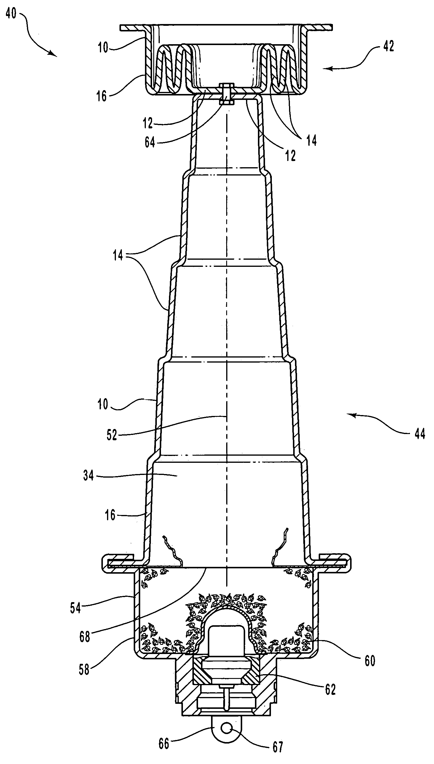
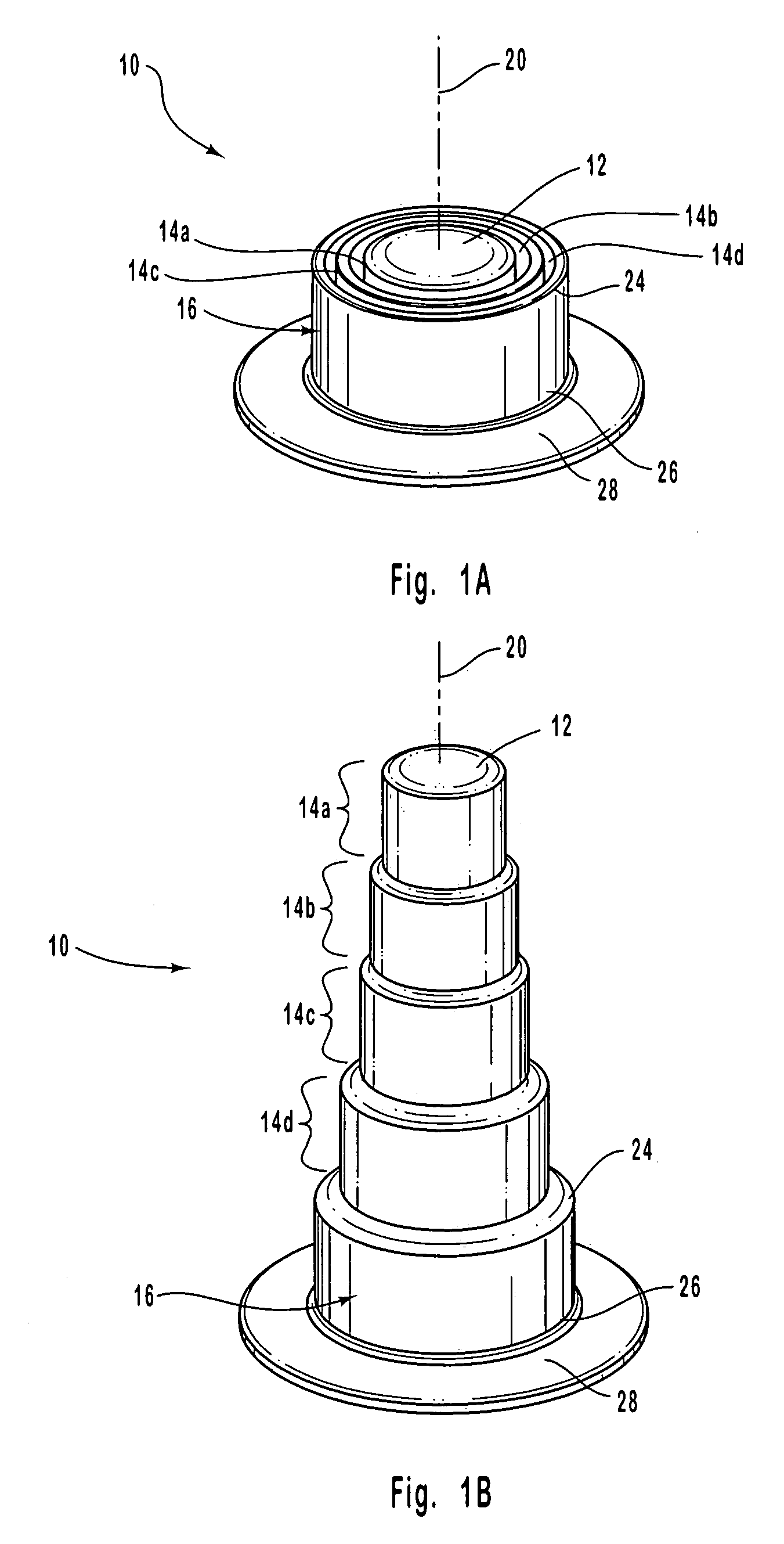
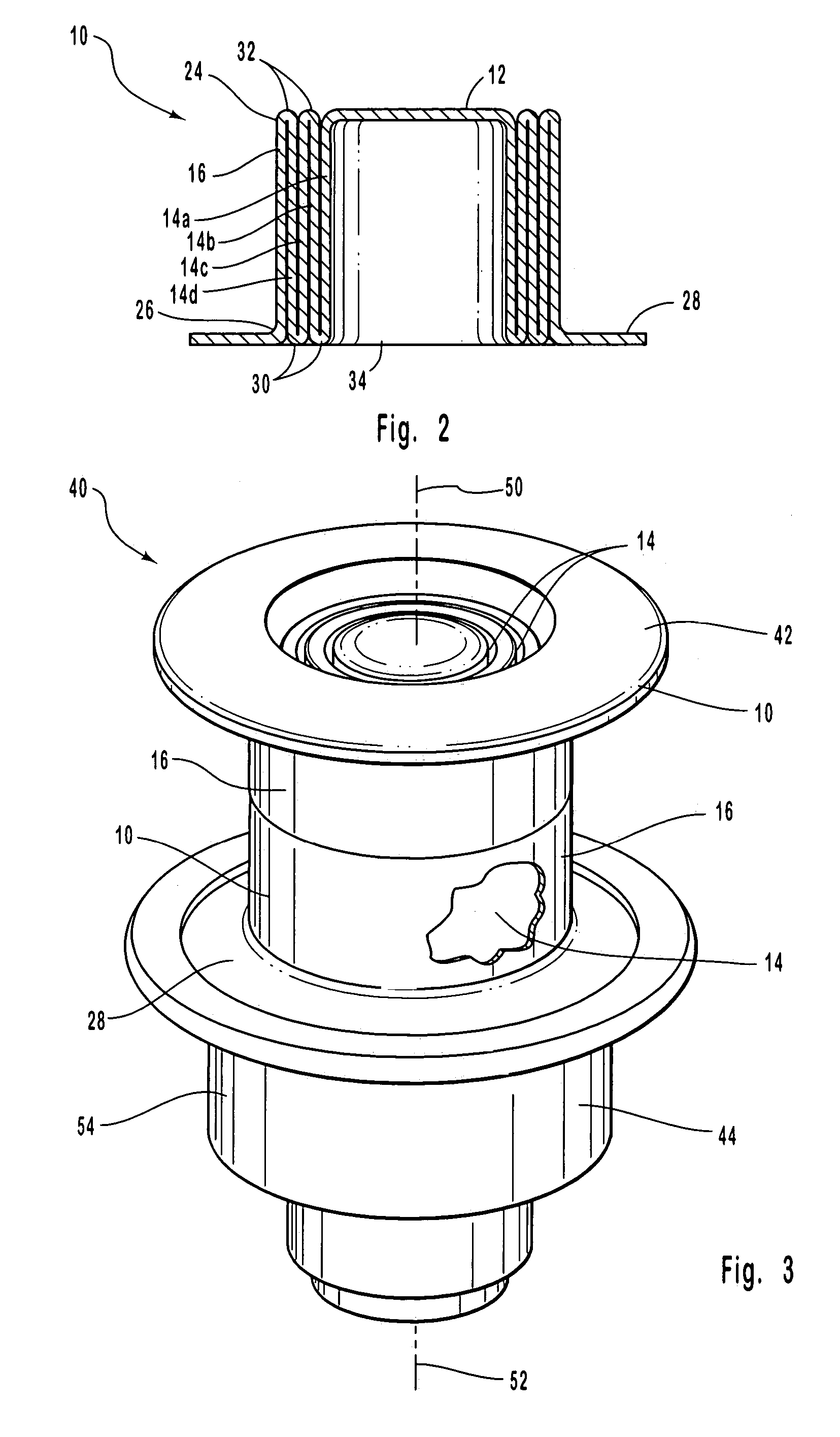
[0038]The preferred embodiments of the invention are now described with reference to FIGS. 1–6, wherein like parts are designated by like numerals throughout. The members of the present invention, as generally described and illustrated in the Figures, may be designed in a wide variety of configurations. Thus, the following more detailed description of the embodiments of the present invention, as represented in the Figures, is not intended to limit the scope of the invention, as claimed, but is merely representative of presently preferred embodiments of the invention.

[0039]In this application, the phrases “connected to,”“coupled to,” and “in communication with” refer to any form of interaction between two or more entities, including mechanical, electrical, magnetic, electromagnetic, and thermal interaction. The phrase “attached to” refers to a form of mechanical coupling that restricts relative translation or rotation between the attached objects. Items, parts, or divisions that are ...


PUM


Abstract

The motion damper includes a damper wall, damper stages, and a damper head. The damper wall and damper stages are successively smaller in size and have a nested relationship. The damper wall and damper stages are each flexibly attached to an adjacent damper stage or the damper wall such that the damper stages may deploy in a telescopic fashion away from the damper wall. The damper head is attached to a smallest damper stage. As a result, the damper stages change in position relative to the damper wall and relative to each other to absorb the kinetic energy of objects attached to the damper head and damper wall.

Description

RELATED APPLICATIONS[0001]This application is a continuation-in-part of patent application Ser. No. 10 / 193,414 filed Jul. 11, 2002 now U.S. Pat. No. 6,907,817 and entitled Linear Actuator, which is incorporated herein by this reference.BACKGROUND OF THE INVENTION[0002]1. Field of the Invention[0003]The present invention relates to a motion damper. More specifically, the invention relates to a motion damper used in connection with vehicle safety systems.[0004]2. Description of Related Art[0005]Conventional dampers are used to limit the transfer of kinetic energy between two connected objects. In today's world, dampers are used in a wide variety of applications. For example, shock absorbers in vehicular suspension systems use a common type of damper. These suspension systems use a spring, such as a steel coil, to allow each wheel to move up when the wheel encounters a bump, and to rapidly move back down after the wheel passes the bump. However, if only the spring were used in the susp...

Claims


Application Information

Patent Timeline
IPC IPC(8): F16F7/12B60N2/23B60N2/42B60N2/427B60P1/16B60R21/00B60R21/34F15B15/10F15B15/16F15B15/19
CPCB60N2/231B60N2/4214B60N2/42745B60P1/162F16F7/125F15B15/10F15B15/16F15B15/19F16F7/123B60R21/34B60R21/00B60R21/38
Inventor SCOTT, JOHNMACARI, JOHNPARKS, BRENT
Owner AUTOLIV ASP INC
Why Eureka
Try Eureka