System and method for manipulating illumination created by an array of light emitting devices

a technology of light emitting devices and arrays, applied in the field of optical systems, can solve the problems of large optics, large optics, and relatively high manufacturing cos

Active Publication Date: 2007-02-27
SIGNIFY HLDG BV
View PDF15 Cites 112 Cited by
  • Summary
  • Abstract
  • Description
  • Claims
  • Application Information

AI Technical Summary

Benefits of technology

[0017]An object of the present invention is to provide a system and method for manipulating illumination created by an array of light emitting devices. In accordance with an aspect of the present invention, there is provided a system for manipulating illumination created by an array of light emitting devices, said system comprising: a plurality of light emitting devices spatially arranged in an array, said array separated into one or more sections, wherein each section of the array includes light emitting devices capable of creating illumination having a predetermined wavelength range; a macroscopic optical system adjacent to the plurality of light emitting devices, said macroscopic optical system enabling redirection of the illumination created by the plurality of light emitting devices; and a microscopic optical system for diffusing the illumination created by the plurality of light emitting devices subsequent to the redirection by the macroscopic optical system, thereby providing a desired level of blending of the predetermined wavelengths ranges.
[0018]In accordance with another aspect of the invention, there is provided a method for manipulating illumination created by an array of light emitting devices, said method comprising the steps of: redirecting the illumination using reflective optics formed in a grid pattern; diffusing the redirected illumination thereby blending the redirected illumination to create a desired illumination effect, said diffusing retaining a desired angular distribution of the illumination created by the reflective optics.

Problems solved by technology

If, however, the LEDs are arranged in linear rows of separate colours, the projected beam of light typically exhibits objectionable colour gradients at its edges.
In addition, surfaces being illuminated using the above mentioned devices, that have occluding objects thereon, results in strong colour banding being visible on the illuminated surface due to the shadow cast by this occluding object.
However these types of optics are bulky and relatively expensive to manufacture.
Furthermore, these forms of refractive optics are unable to preferentially redirect emitted illumination in an off-axis direction, with respect to the plane of the array of LEDs, however this is possible if the LEDs are mounted at an angle with respect to the plane of the array.
In order to enable this type of mounting, each LED could be mounted and wired separately to enable this form or orientation, however this would preclude the use of a common circuit board for the mounting of the LEDs, as is a current standard, thereby resulting in a more costly device.
A further disadvantage of the prior art is that red, green and blue LEDs typically require different drive voltages and can produce ranging colours of light, as such binning of LEDs is typically performed, in order to ensure a uniform illumination colour being produced by an array of LEDs.
As has been previously mentioned, linear arrays of LEDs are difficult to incorporate into current lighting devices due to the problems of colour gradients and colour banding.
This lighting fixture is designed specifically for use with fluorescent lamps and as such does not provide a means for manipulating the illumination provided by a plurality of discrete light sources that produce different wavelengths of illumination.
However this diffuser has not been designed to provide the blending of colours produced by a plurality of discrete light sources in close proximity.
This design of a diffuser enables colour mixing specifically designed for the situation where there is close proximity between the various colours of light and therefore may not be effective in blending illumination produced by a first strip of light emitting devices producing a first colour that is flanked by a second strip producing a different illumination colour.

Method used


Image

  • System and method for manipulating illumination created by an array of light emitting devices
  • System and method for manipulating illumination created by an array of light emitting devices
  • System and method for manipulating illumination created by an array of light emitting devices

Examples


example 1

Optical System for Predominantly Horizontal Distribution of Illumination

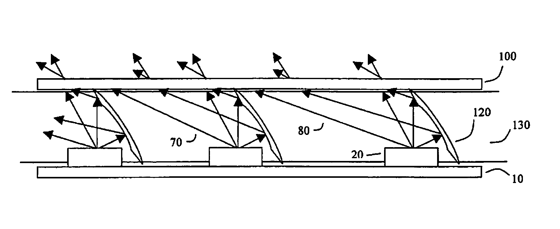
[0059]In one embodiment of the present invention, the illumination optical system is designed for a predominantly horizontal distribution of the illumination created by the light emitting devices. FIG. 9 illustrates three components of an optical system meeting this criterion, wherein the optical system comprises a two dimension array of light emitting devices 205 on collection of aligned linear printed circuit boards, 200, a macroscopic optical system 210 incorporating horizontal reflective optics 310 and a microscopic optical system 220 in the form of a diffuser. Cross sections A—A and B—B of the illumination optical system are illustrated in FIGS. 10 and 11, respectively. While the cross section is identified on the macroscopic optical system, the cross section illustrates a cross section of the three components together.

[0060]The macroscopic optical system that includes a plurality of horizontal planar refle...

example 2

Optical System for Predominantly Vertical Distribution of Illumination

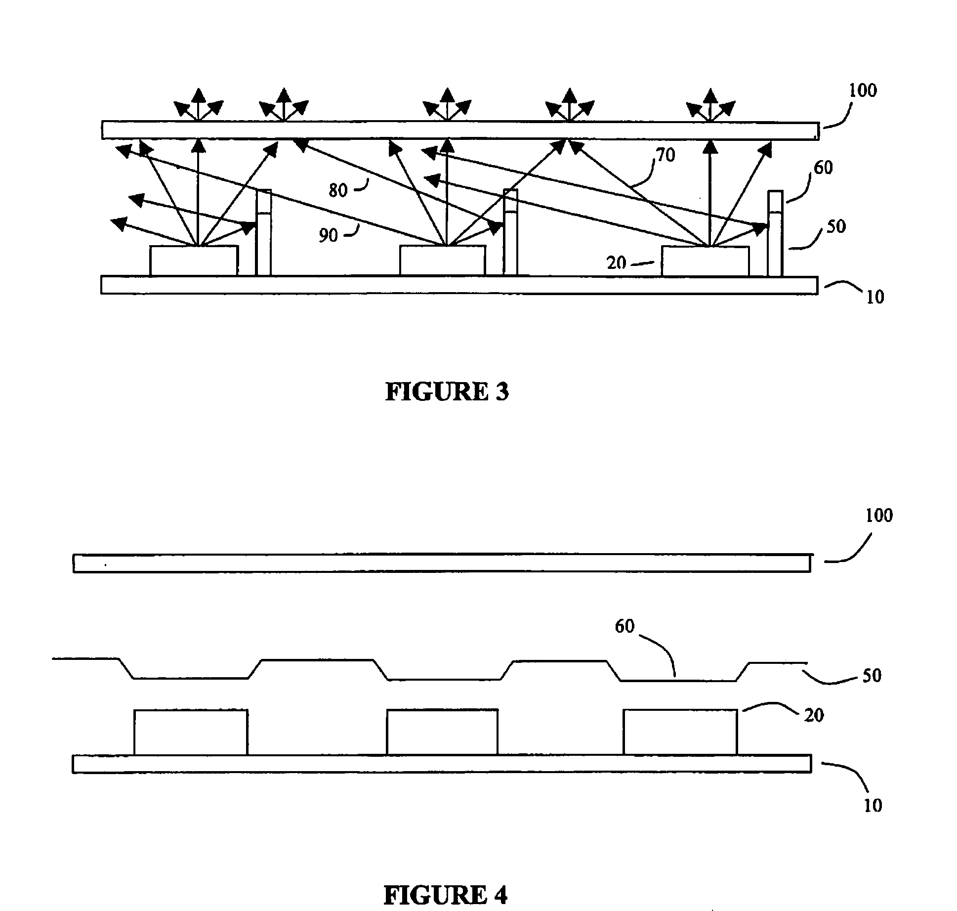
[0062]In one embodiment of the present invention, the illumination optical system is designed for a predominantly vertical distribution of the illumination created by the light emitting devices. FIG. 13 illustrates three components of an optical system meeting this criteria, wherein the optical system comprises a two dimension array of light emitting devices 205 on collection of aligned linear printed circuit boards, 200, a macroscopic optical system 230 incorporating tilted and curved horizontal reflective optics 340 and vertical parabolic trough reflective optics 330, together with a microscopic optical system 240 in the form of a diffuser. Cross sections C—C and D—D of the illumination optical system are illustrated in FIGS. 14 and 15, respectively. While the cross section is identified on the macroscopic optical system, the cross section illustrates a cross section of the three components together.

[0063]The ma...


PUM


Abstract

The present invention provides an illumination optical system that enables the direction and mixing of light from light emitting devices. The optical system comprises a plurality of light emitting devices that are spatially arranged in an array, wherein this array comprises one or more sections, such that the light emitting devices in a particular section emit light within a predetermined wavelength range. Through the use of a combination of macroscopic and microscopic optical systems, the illumination created by the array can be manipulated such that a desired illumination distribution is created. The macroscopic optical system provides a means for redirecting the illumination in one or more desired directions, wherein this redirection is provided by a collection of appropriately shaped and positioned reflective optics. Subsequent to its interaction with the macroscopic optical system, the illumination is manipulated by a microscopic optical system that enables the diffusion of the illumination in a predetermined manner, while retaining the desired angular distribution of the illumination created by the macroscopic optical system. Through the appropriate design and orientation of both the macroscopic and microscopic optical systems, a desired illumination effect can be created.

Description

CROSS REFERENCE TO RELATED APPLICATION[0001]This application claims the benefit of priority under 35 U.S.C. § 119(a) of Canadian Application No. 2,420,939 filed Mar. 5, 2003, the entire content of which is incorporated herein by reference.BACKGROUND OF THE INVENTION[0002]1. Field of the Invention[0003]The present invention pertains to the field of optical systems and in particular to an optical system incorporating solid-state light emitting devices configured in an array.[0004]2. Background Information[0005]Recent innovations in LED design and manufacturing have led to the introduction of high-brightness LEDs that produce sufficient luminous flux for architectural and entertainment lighting applications. LEDs with different wavelength ranges, for example, red, green, and blue, have been combined in arrays with ancillary refractive optics to generate user-specified colours. An example of this type of configuration is the Space Cannon Metamorphosis™ (Space Cannon vH, Fubine, Italy), ...

Claims


Application Information

Patent Timeline
Patent Type & Authority Patents(United States)
IPC IPC(8): F21V13/00F21V5/00F21V13/04
CPCF21S4/008F21V5/002F21V13/04F21Y2103/003F21Y2101/02F21S4/28F21Y2103/10F21Y2115/10
Inventor KAN, PETER
Owner SIGNIFY HLDG BV
Why Eureka
Try Eureka