Battery pack

a battery pack and battery technology, applied in the field of batteries, can solve the problems of b>1/b> not being able to operate normally, the control circuit b>40/b> cannot operate normally, and the portable cellular phone cannot be operated, etc., to achieve the effect of simplifying the configuration, simplifying the configuration, and maximizing the capacity of the fuel cell

Inactive Publication Date: 2007-02-27
TOKIN CORP
View PDF13 Cites 15 Cited by
  • Summary
  • Abstract
  • Description
  • Claims
  • Application Information

AI Technical Summary

Benefits of technology

[0015]In view of the above, it is an object of the present invention to provide a battery pack which is capable of operating a portable cellular phone immediately even when a dedicated secondary battery is discharged.
[0072]Moreover, since the primary battery produces electromotive force having a voltage being same as that of the dedicated secondary battery and the power storing section is made up of the electrical double layer capacitor having an equivalent serial resistance being lower than that of the primary battery, a current limiting circuit and DC / DC converter are not required, which can simplify its configurations. Also, since the battery pack is provided with a fuel cell, when fuel runs out, by supplementing the fuel, operations of the battery pack can be immediately restored to its normal state. Since the fuel cell generates electromotive force having a same voltage as that of the dedicated secondary battery and since the power storing section has an equivalent serial resistance being lower than the fuel cell, the current limiting circuit and DC / DC converters are not required, which can simplify its configurations. Since almost no drop occurs in a voltage of the electrical double layer capacitor (power storing section) even while power consumption increases or decreases in a burst manner, capacity of the fuel cell can be utilized to the fullest.

Problems solved by technology

However, the above conventional battery pack 30 has following problems to be solved.
Another problem is that, since the dedicated secondary battery 20 makes up part of components of a power source section of the portable cellular phone 1, if a failure occurs in the dedicated secondary battery 20, the portable cellular phone 1 cannot be operated even by the connection of the battery pack 30.
Moreover, there is still another problem that, since the charge controlling circuit 40 is configured assuming that the dedicated secondary battery 20 is charged, if the dedicated secondary battery 20 is lost, the charge controlling circuit 40 does not operate normally in some cases and, as a result, a voltage required to normally operate the portable cellular phone 1 cannot be obtained even by the connection of the battery pack 30.
Also, still another problem is that, since a voltage required for operating the charge controlling circuit 40 is 4V, it is necessary for the battery pack 30 to have at least three battery cells (each having a voltage of 1.5V) being connected in series, which thus causes a user to feel that the portable cellular phone 1 is heavy to carry.
Furthermore, the conventional portable cellular phone presents another problem in that, when the battery pack 30 is connected to its multifunctional connector 12, other devices such as personal computers or a like cannot be connected to the multifunctional connector 12.
However, this method has a problem in that not only carrying the dedicated secondary battery is attended with risk of occurrence of a short circuit but also buying such the backup dedicated secondary battery is costly.
Moreover, in this case, a user has to carry an AC adapter required to charge such the dedicated backup second battery.
As a result, in some cases, a message that the voltage has reached its final level even in a state where a discharging depth of the dedicated secondary battery 20 is shallow (that is, battery capacity is still residual somewhat) appears on a displaying section of the portable cellular phone 1, which presents another problem that battery capacity cannot be used to the fullest.

Method used


Image

  • Battery pack
  • Battery pack
  • Battery pack

Examples


first embodiment

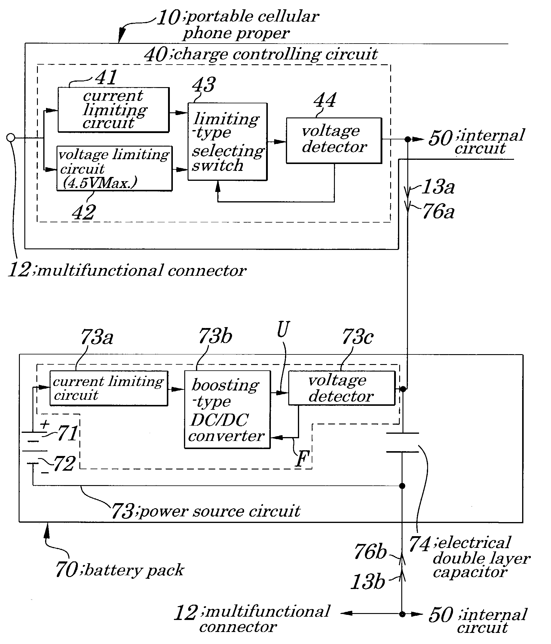
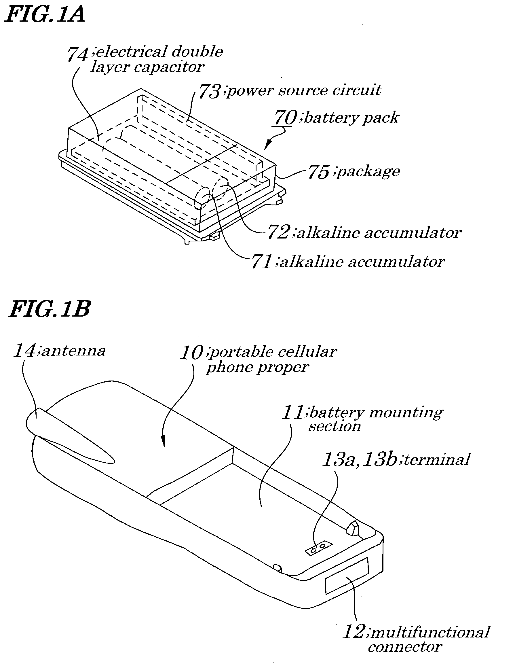
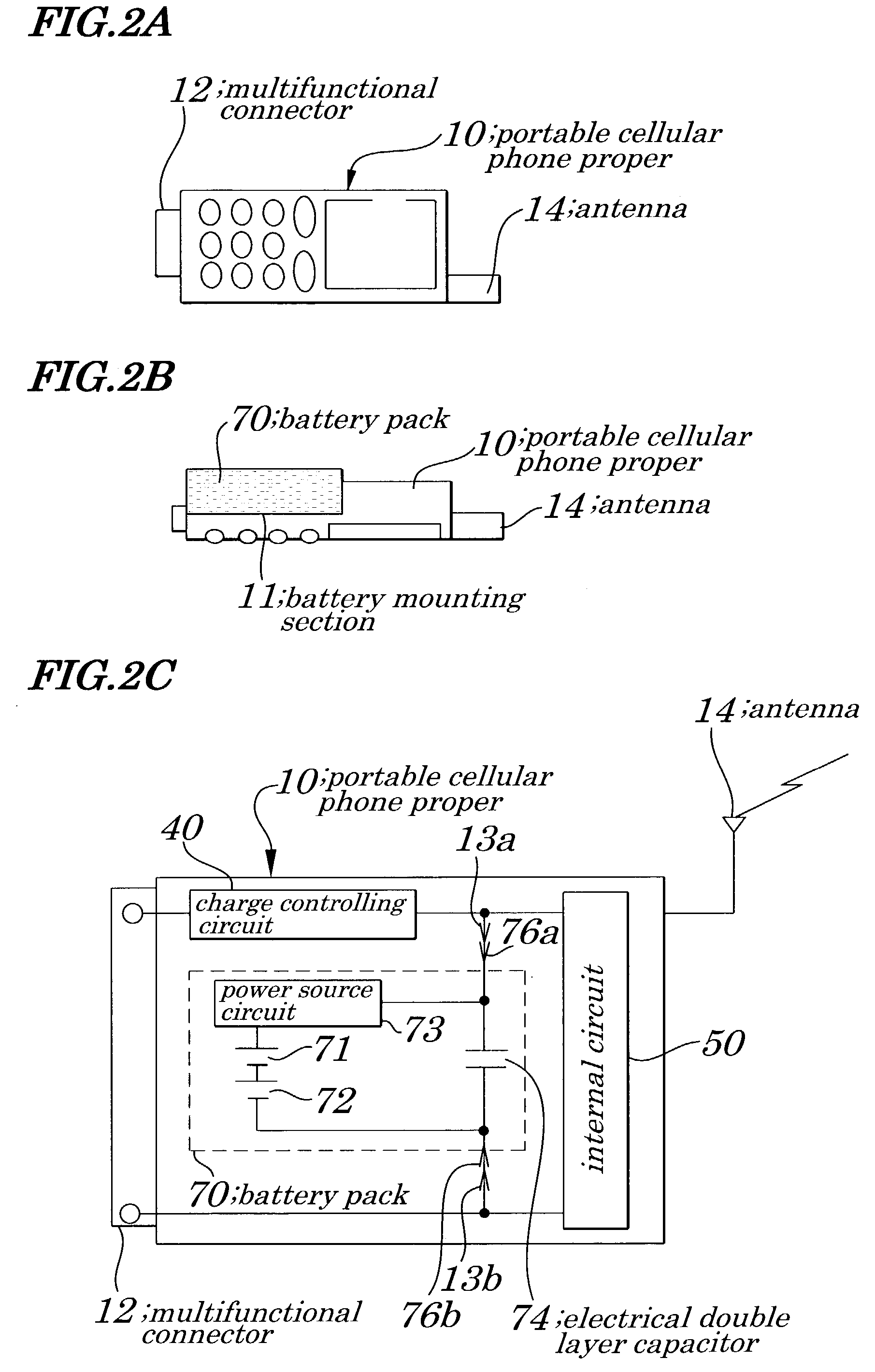
[0090]FIG. 1A is a perspective view showing a battery pack 70 and FIG. 1B is a perspective view showing a battery mounting section 11 of a portable cellular phone proper 10 according to a first embodiment of the present invention. A battery pack 70 of the first embodiment, as shown in FIG. 1A is made of alkaline accumulators 71 and 72, a power source circuit 73, an electrical double layer capacitor 74, and a package 75 to house them, and is placed in a portable cellular phone proper 10 instead of conventional detachable dedicated secondary battery 20 as shown in FIG. 12A. FIGS. 2A, 2B, and 2C are diagrams illustrating the portable cellular phone with the battery pack 70 shown in FIG. 1A being placed in the portable cellular phone proper 10 and the battery pack 70 of FIGS. 1A and 1b. FIG. 2C is a circuit diagram showing electrical configurations of the portable cellular phone of FIGS. 1A and 1B. In FIGS. 2A to 2C, same reference numbers are assigned to components having same function...

second embodiment

[0097]FIGS. 5A and 5B are perspective views showing a battery pack 70A and a battery mounting section 11 of a portable cellular phone proper 10 according to a second embodiment of the present invention. In FIGS. 5A and 5B, same reference numbers are assigned to components having same functions as those in FIGS. 1A and 1B. In the battery pack 70A of the second embodiment, as shown in FIG. 5A, a power source circuit 73 is removed from the battery pack 70A and an alkaline accumulator 77 is additionally provided. Other components are same as those in FIGS. 1A and 1B and their description is omitted for brevity.

[0098]FIGS. 6A, 6B and 6C are diagrams illustrating a portable cellular phone in which its battery pack 70A shown in FIG. 5A is placed in a portable cellular phone proper 10 (FIG. 5B) of the second embodiment of the present invention. In FIGS. 6A, 6B, and 6C, same reference numbers are assigned to components having same functions as those in FIGS. 2A, 2B, and 2C. As shown in FIG. ...

third embodiment

[0101]FIGS. 7A and 7B are perspective views showing a battery pack 70B and a battery mounting section 11 of a portable cellular phone proper 10 according to a third embodiment of the present invention. In FIGS. 7A and 7B, same reference numbers are assigned to components having same functions as those in FIGS. 1A and 1B and description of some parts have been omitted. In the battery pack 70B of the third embodiment, as shown in FIGS. 7A and 7B, instead of alkaline accumulators 71 and 72 shown in FIGS. 1A and 1B, a fuel cell 78 is provided. Other configurations are same as those in FIGS. 1A and 1B.

[0102]FIGS. 8A, 8B, and 8C are diagrams illustrating a portable cellular phone in which its battery pack 70B shown in FIG. 7A is placed in the portable cellular phone proper 10 of the first embodiment of the present invention. In FIGS. 8A, 8B, and 8C, same reference numbers are assigned to components having same functions as those in FIG. 2. As shown in FIG. 8C, in the battery pack 70B, the...


PUM

PropertyMeasurementUnit
electromotive forceaaaaaaaaaa
voltageaaaaaaaaaa
voltageaaaaaaaaaa

Abstract

A battery pack is provided which can be suitably used in a case where charging of a dedicated secondary battery in a portable terminal device is difficult. The battery pack is mounted in a battery mounting section in a portable cellular phone (portable terminal device) proper. In the battery pack, alkaline accumulators are connected in series. Alkaline accumulators generate electromotive forces having a voltage (3V) being lower than that of the dedicated secondary battery. A power source circuit has a boosting-type DC / DC converter which boosts a voltage of the alkaline accumulators being connected in series at a level being same as that of the dedicated secondary battery (for example, 4.5V), and outputs the boosted voltage. An electrical double layer capacitor has a capacity to feed stable power to an internal circuit in which power consumption increases or decreases in a burst manner and is charged by application of an output of the power source circuit and stores the power.

Description

BACKGROUND OF THE INVENTION[0001]1. Field of the Invention[0002]The present invention relates to a battery pack and more particularly to the battery pack that can be suitably used for a portable terminal device such as a portable cellular phone being carried by for example a user who is on the road over an extended period of time.[0003]The present application claims priority of Japanese Patent Application No. 2002-079802 filed on Mar. 20, 2002, which is hereby incorporated by reference.[0004]2. Description of the Related Art[0005]Generally, a portable terminal device such as a portable cellular phone 1 is so configured as to operate using its dedicated secondary battery 20. For example, as shown in FIGS. 12A and 12B, the portable cellular phone 1 is made up of a main body of portable cellular phone 10 and the dedicated secondary battery 20. As shown in FIGS. 12A and 12B, the main body of portable cellular phone 10 has a battery mounting section 11, a multifunctional connector 12, te...

Claims


Application Information

Patent Timeline
Patent Type & Authority Patents(United States)
IPC IPC(8): H01M16/00H01M6/50H01M6/00H01M6/42H01M8/00H01M50/213H01M50/244H01M50/247H02J7/34H04M1/02
CPCH01M6/50H01M6/5033H04M1/0262H01M16/00H02J7/345H01M6/00H01M6/42H01M16/003H01M8/00Y02E60/50H04B1/40
Inventor SASAKI, HIROSHIINOI, TAKAYUKI
Owner TOKIN CORP
Why Eureka
Try Eureka