Motor control device and motor control method

a technology of motor control and control device, which is applied in the direction of electric controllers, ignition automatic control, instruments, etc., can solve the problems of premature current detection, affecting the protection function of overcurrent, and affecting the accuracy of sampling and holding. achieve the effect of high accuracy

Inactive Publication Date: 2007-02-27
ASMO CO LTD
View PDF3 Cites 1176 Cited by
  • Summary
  • Abstract
  • Description
  • Claims
  • Application Information

AI Technical Summary

Benefits of technology

[0008]Accordingly, it is an objective of the present invention to provide a motor control device and a motor control method that are capable of detecting a current flowing through a motor with high accuracy.

Problems solved by technology

Therefore, if the sampling and holding of the motor current is started at the aforementioned timing, which corresponds to the middle of the activation time of the PWM control signal, the sampling and holding may be completed prematurely, or before the motor current becomes sufficiently large.
In this device, if sampling and holding of the motor current is performed at the aforementioned timing, which corresponds to the middle of the activation time of the PWM control signal, the premature current detection may hamper the overcurrent protecting function.
However, since the motor current is varied relatively greatly following the trailing edge of the PWM control signal, the detected current may be inaccurate.
This also hampers the overcurrent protecting function.

Method used


Image

  • Motor control device and motor control method
  • Motor control device and motor control method
  • Motor control device and motor control method

Examples


first embodiment

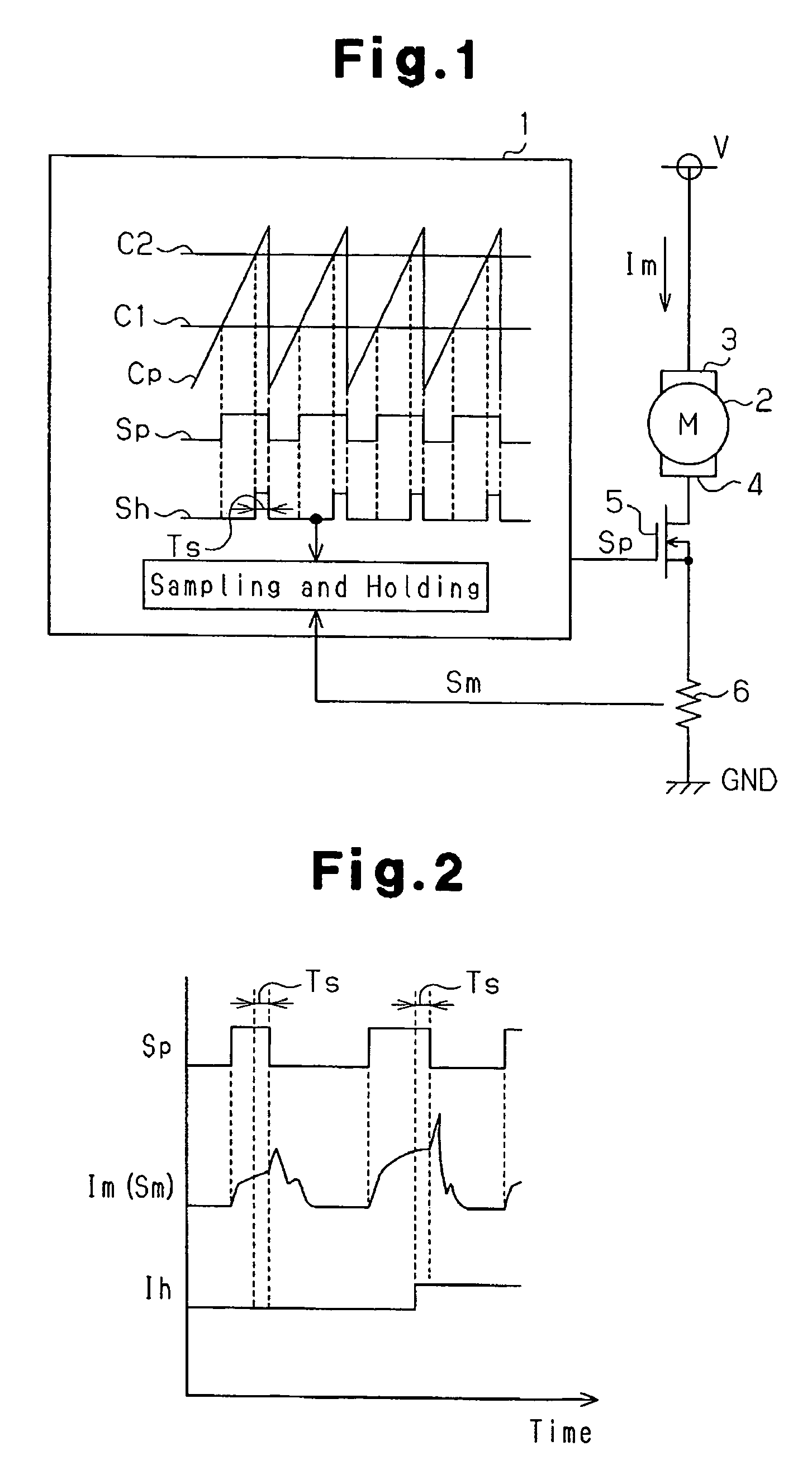
[0020]the present invention will hereafter be described with reference to FIGS. 1 and 2.

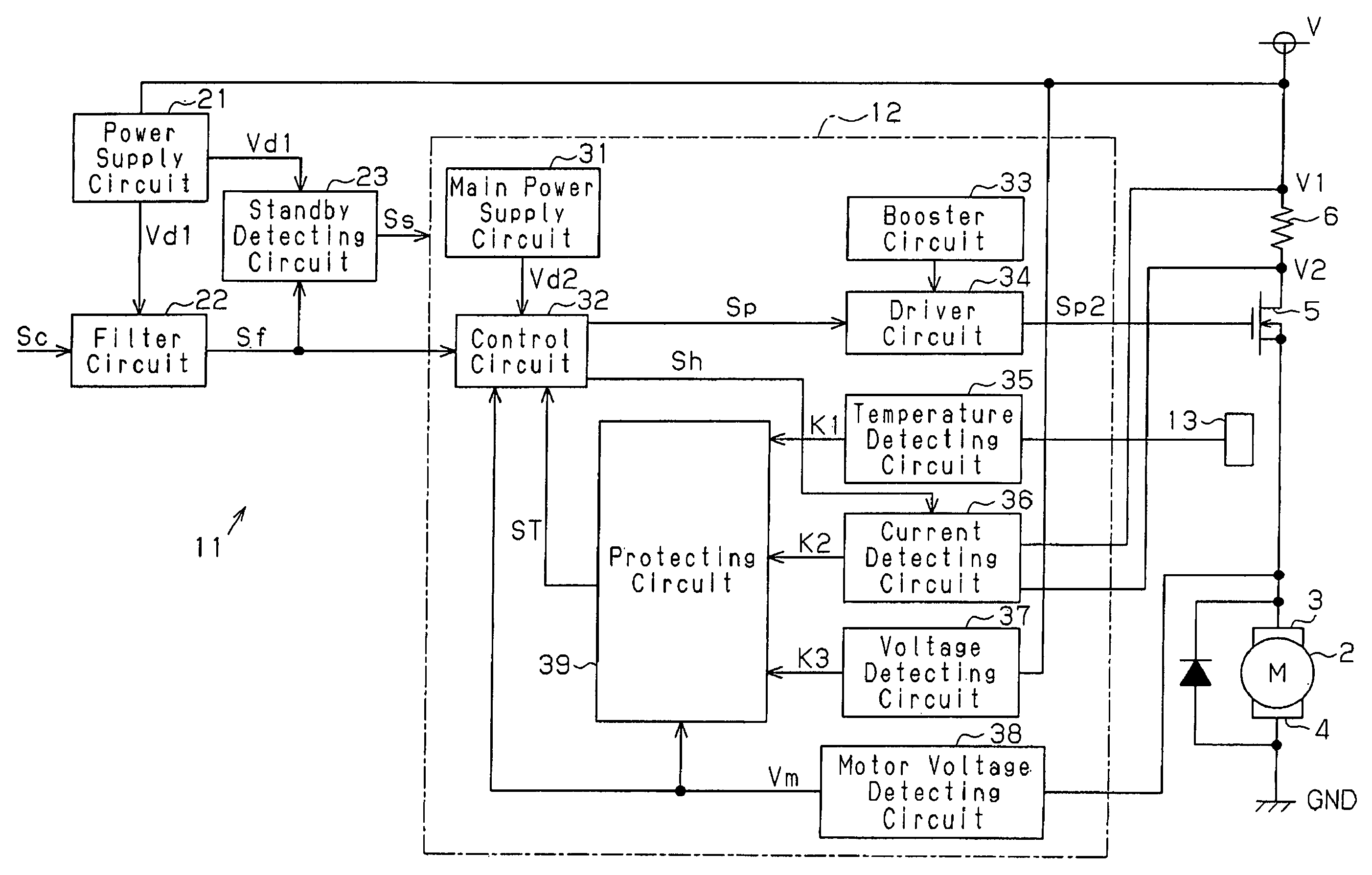
[0021]As illustrated in FIG. 1, a motor control device 1 according to the present invention controls the speed of an air blowing motor 2 for a vehicle air conditioner in accordance with pulse width modulation (PWM) controlling. The control device 1 also has an overcurrent protecting function for protecting the motor 2 from an overcurrent. The motor 2 includes a power terminal 3 connected to the plus side of a DC power supply V (a battery). An opposed power terminal 4 of the motor 2 is connected to the ground GND through a drive transistor 5, which serves as a switching element such as an FET, and a resistor 6. The control device 1 sends a PWM control signal Sp, or a control signal, to a control terminal (a gate terminal) of the drive transistor 5. The drive transistor 5 is turned on or off selectively in accordance with the PWM control signal Sp. The drive transistor 5 supplies a drive current Im...

second embodiment

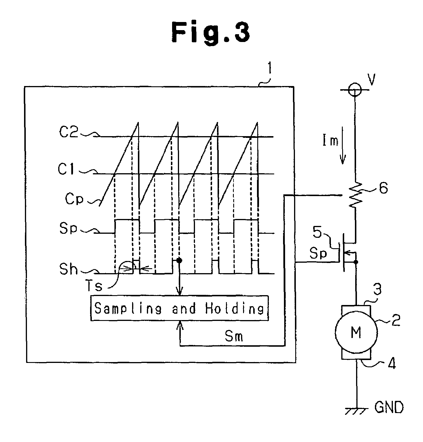
[0030]the present invention will hereafter be described with reference to FIGS. 3 to 7.

[0031]As illustrated in FIG. 3, a motor control device 1 of the second embodiment controls, like the first embodiment, the speed of an air blowing motor 2 for a vehicle air conditioner, in accordance with pulse width modulation (PWM) controlling. The control device 1 also has an overcurrent protecting function for protecting the motor 2 from an overcurrent. The motor 2 includes a power terminal 3 connected to the plus side of a DC power supply V (a battery) through a drive transistor 5, which serves as a switching element such as an FET, and a resistor 6. An opposed power terminal 4 of the motor 2 is connected to the ground GND.

[0032]The control device 1 receives an instructing signal Sc and generates a control signal Sp having a duty ratio varied depending on the instructing signal Sc. The control signal Sp is then inputted to a control terminal (a gate terminal) of the drive transistor 5, which ...


PUM


Abstract

A motor control device selectively turns on or off a drive transistor in-accordance with a PWM control signal Sp, such that a drive current Im supplied to a motor is adjusted. The device also samples and holds a motor current Sm for obtaining a motor current value Ih. With reference to the motor current value Ih, the device protects the motor from an overcurrent. Sampling and holding of the motor current Sm is performed for a sampling and holding time Ts. The sampling and holding time Ts corresponds to a time period between a first point in time when the level of the PWM control signal Sp is switched for turning off the drive transistor and a second point in time that precedes the first point in time by a predetermined period. As a result, the motor current value Ih is detected with high accuracy.

Description

BACKGROUND OF THE INVENTION[0001]The present invention relates to a device and a method for controlling a motor based on a current flowing through the motor.[0002]As a method for controlling the speed of a motor, the pulse width modulation (PWM) controlling is known. Such technique is described in, for example, Japanese Laid-Open Patent Publication No. 6-237591. More specifically, a PWM control signal is supplied to a field effect transistor (FET), which supplies a drive current to the motor, such that the FET is selectively turned on or off. A resistor is connected in series with the motor for detecting a current flowing through the motor. The detection is achieved by sampling and holding the current flowing through the motor for a time sufficiently shorter than the time for which the PWM control signal remains activated. The timing for sampling and holding the motor current is set at the middle of the activation time of the PWM control signal. The duty ratio of the PWM control sig...

Claims


Application Information

Patent Timeline
Patent Type & Authority Patents(United States)
IPC IPC(8): G05B11/18H02P7/29
CPCH02P7/28H02P29/028H02P29/0088H02P29/032H02P29/68
Inventor KITAGAWA, TAKAYUKI
Owner ASMO CO LTD
Why Eureka
Try Eureka