Motor control device

a technology of motor control and control device, which is applied in the direction of electric controllers, ignition automatic control, instruments, etc., can solve the problems of speed fluctuations, high accuracy control, and large torque, and achieve high accuracy control, stability no longer weakened, and maintain the stability of the control system

Active Publication Date: 2007-02-27
MITSUBISHI ELECTRIC CORP
View PDF5 Cites 11 Cited by
  • Summary
  • Abstract
  • Description
  • Claims
  • Application Information

AI Technical Summary

Benefits of technology

[0022]As described above, according to the first aspect of the invention, since the filter is set so that the phase is delayed between the resonance frequency and the anti-resonance frequency of the mechanical system, it is possible to enlarge the gain at low frequencies while maintaining the stability of the control system. By this means, the speed fluctuations due to the disturbing torque become small, and the effect is obtained of being able to realize high-accuracy control.
[0028]According to the seventh aspect of the invention, the parameter setting means configures so that the filter phase is delayed between the anti-resonance frequency and the resonance frequency of the mechanical system based on the frequency response of the mechanical system acquired by the frequency response acquisition means, so that the phase lag of the filter is cancelled by the phase advance of the mechanical system. As a result, the phase lags at the first crossover frequency ωC1 and the second crossover frequency ωC2 do not become large, and even when the filter is inserted, the effect is obtained that the stability is no longer weakened.

Problems solved by technology

However, with machines having low rigidity, since the gain is small at low frequencies as described above, the speed fluctuations due to the disturbing torque become large and high accuracy control becomes difficult.
However, there is a limit to this, and ultimately high accuracy control could not be realized.
However, when the proportional gain KP is made large, since the second crossover frequency ωC2 shifts to the high frequency side, the phase lag for the second crossover frequency ωC2 becomes large and the control system ends up vibrating and oscillating.
In this way, since for the conventional speed control device it is not possible to enlarge the proportional gain KP or the integral gain KI beyond a certain amount, the gain at low frequencies cannot be made large, and as a result high accuracy control has been difficult.
However, this technology is mainly directed less at the resonance peak illustrated in FIG. 7, than at restraining the unstable resonance peak at higher frequencies, and it is inexpedient to apply this technology to stable resonance peaks such as in FIG. 7.
As a result, the disadvantage occurs that even when the mechanical system vibrates at the resonance frequency, the speed control system cannot stop this vibration.
As described above, when controlling a mechanical system of low rigidity and where the inertial moment J of the mechanical system is large in comparison to the inertial moment JM of the motor, there have been problems in that it is difficult to make the gain large at low frequencies with the conventional generally-used speed control device, and speed fluctuations due to disturbing torque become large so that high accuracy control is difficult.
Furthermore, the technology disclosed in Japanese Laid-Open Patent Publication 2000-322105 enables the gain to be made large at low frequencies but cannot stop mechanical vibration, so that it could not be applied to mechanical systems having mechanical vibration at low frequencies.

Method used


Image

  • Motor control device
  • Motor control device
  • Motor control device

Examples


embodiment 1

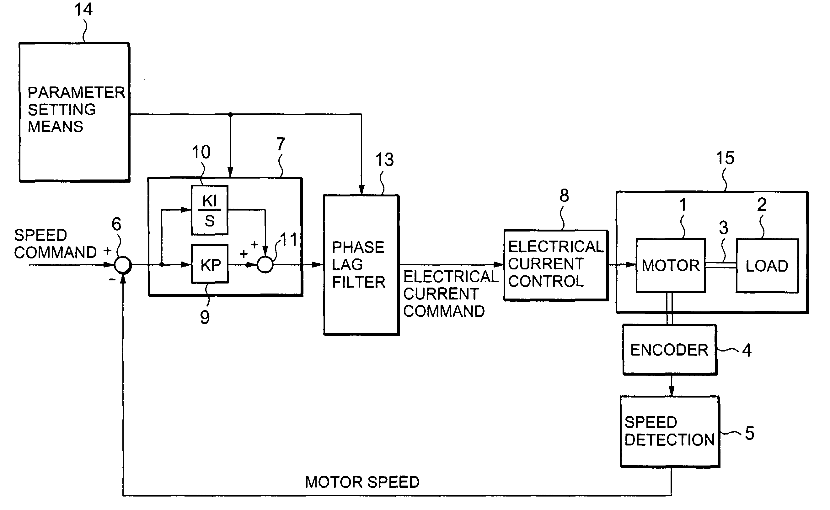
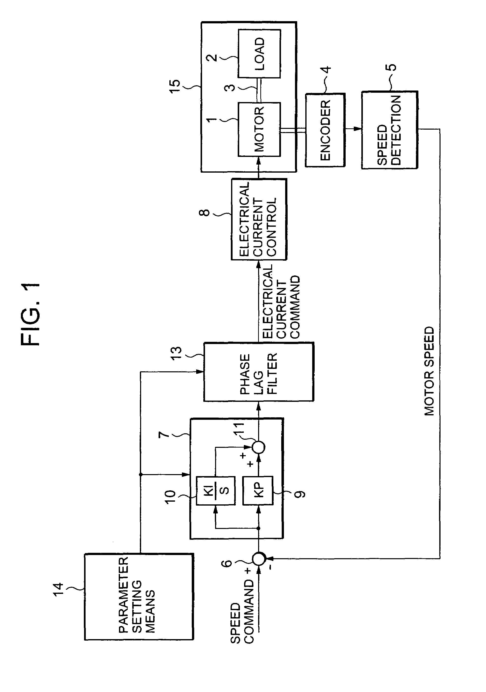
[0038]A first embodiment of the present invention is explained by referring to the configuration block diagram of a control device illustrated in FIG. 1.

[0039]In FIG. 1, identical reference numerals are used for members that are identical or equivalent to those in FIG. 1, and corresponding explanations are omitted. In the figure, reference numeral 1 denotes a motor, reference numeral 2 denotes a load driven by the motor, and reference numeral 3 denotes an axle connecting the motor 1 and the load 2. The load 2 represents a moveable member of a machine driven by the motor 1, modeled as one inertial load, and the axle 3 models a mechanism for transmitting torque, generated by the motor 1, to the machine. Reference numeral 4 denotes an encoder as a position detection means, attached to the motor 1, for detecting the position of the motor 1, reference numeral 5 denotes a speed detection means for computing the motor 1 speed by differentiating the motor position detected by the encoder 4....

embodiment 2

[0054]FIG. 4 is a block diagram illustrating a configuration of the control device according to another embodiment of the present invention. Identical reference numerals are used for members that are identical to those in FIG. 1, and corresponding explanations are omitted. In FIG. 4, reference numeral 16 denotes a parameter setting means for setting characteristics for the phase lag filter and the integral gain KI, being a parameter for the speed control means; its operations are approximately the same as for the parameter setting means in FIG. 1 but one of the adjustment parameters a has to be input from outside.

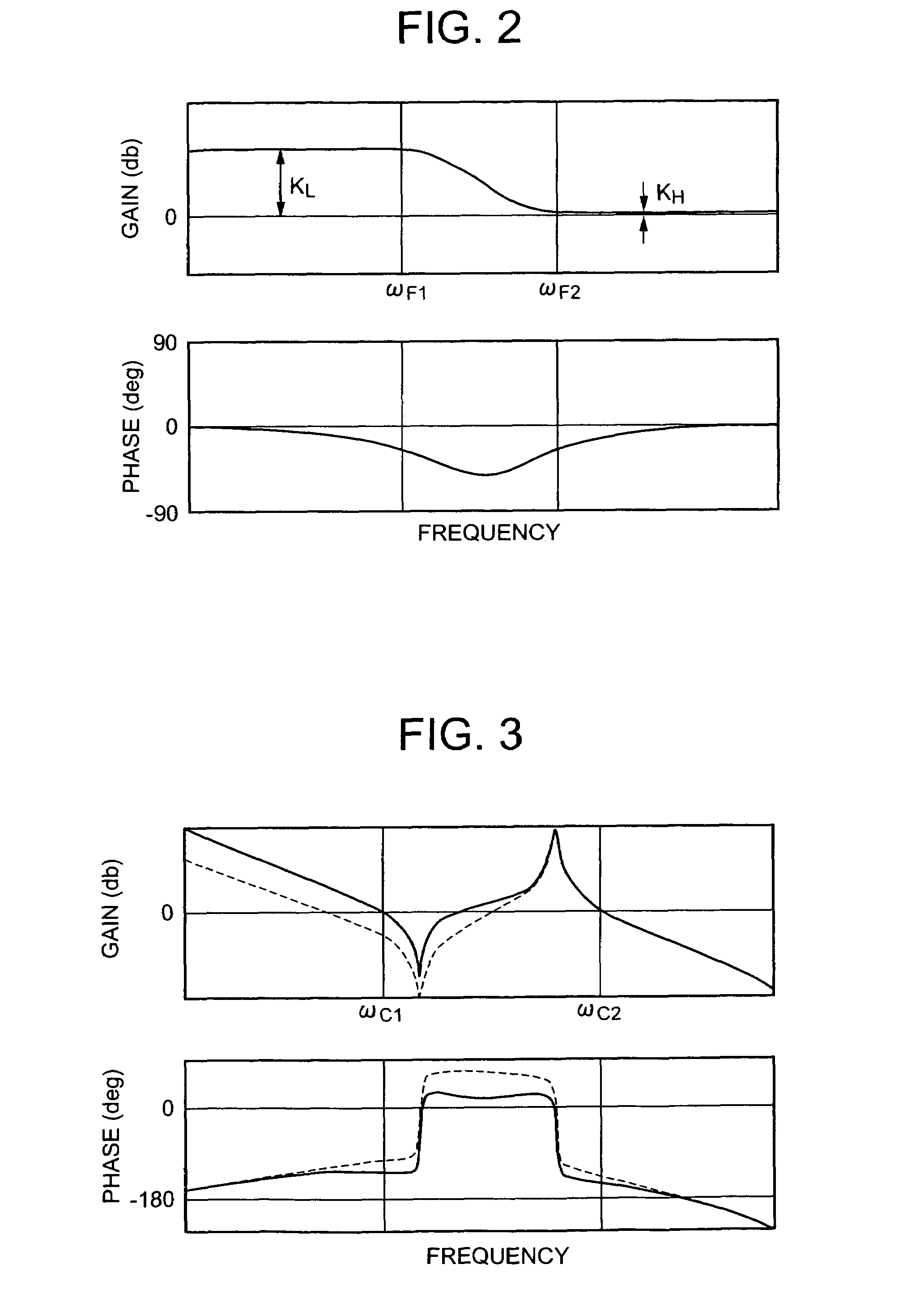
[0055]This adjustment parameter a indicates the ratio of the gain KL against the gain KH at high frequencies, for the phase lag filter 13. In the parameter setting means 16, using the adjustment parameter α, with KL=α×KH, the first crossover frequency ωC1 is computed using the above equation (3). Further, as described above, the first filter frequency ωF1 is set so that the...

embodiment 3

[0063]FIG. 5 is a block diagram illustrating a configuration of the control device according to another embodiment of the invention. The same reference numerals are used for members as in FIG. 1. In FIG. 5, reference numeral 17 denotes a frequency response acquisition means for acquiring frequency response of the mechanical system, reference numeral 18 denotes the parameter setting means for setting the characteristics of the phase lag filter; and the characteristics of the phase lag filter are set based on the frequency response of the mechanical system acquired by the frequency response acquisition means 17.

[0064]Several methods are known for acquiring the frequency response of the mechanical system by the frequency response acquisition means 17. Measurement may be performed using a specialized measurement device, or the motor may be driven at random torques and a frequency analysis can be carried out on the corresponding speed response. Further, in cases where the rigidity, mass,...


PUM


Abstract

A speed control means 7 for outputting a drive command signal for a motor 1 to make the speed of the motor 1 conform to the speed command signal based on a signal indicating the difference between the speed command signal and the detected speed of the motor; a filter 13 inserted in series with the speed control means 7 in the speed control loop, having a high frequency domain, a low frequency domain, and an intermediate frequency domain between the high frequency domain and the low frequency domain, a gain KL in the low frequency domain being larger than a gain KH in the high frequency domain, and having a phase lag characteristic so that the phase in the intermediate frequency domain is delayed; the speed control means 7 having a proportional controller 9 that multiplies input by a proportional gain KP and outputs the result, and the filter 13 being set so that phase lag occurs between a resonance frequency and an anti-resonance frequency of a mechanical system.

Description

BACKGROUND ART[0001]FIG. 6 is a conceptual view of the configuration of a generally used conventional speed control device for a motor. In the figure, reference numeral 1 denotes a motor, reference numeral 2 denotes a load driven by the motor, and reference numeral 3 denotes an axle connecting the motor 1 and the load 2. The load 2 represents a moveable member of a machine driven by the motor 1, modeled as an inertial load, and the axle 3 models a mechanism for transmitting torque, generated by the motor 1, to the machine. Reference numeral 4 denotes an encoder, attached to the motor 1, for detecting the position of the motor 1, reference numeral 5 denotes a speed detection means for computing motor speed by differentiating the motor position detected by the encoder 4. Reference numeral 6 is a comparator for comparing a speed command signal given by a high-level controller (not illustrated in the figure) with the motor speed output by the speed detection means 5, and for outputting ...

Claims


Application Information

Patent Timeline
Patent Type & Authority Patents(United States)
IPC IPC(8): G05B1/02G05B11/06H02P29/00G05B11/36G05B11/42
CPCG05B11/06G05B11/42H02P29/0005H02P6/181H02P6/001H02P6/34H02P29/10
Inventor IKEDA, HIDETOSHIMIYAZAKI, TOMOHIRO
Owner MITSUBISHI ELECTRIC CORP
Why Eureka
Try Eureka