Airborne inventory and inspection system and apparatus

an inventory and inspection system technology, applied in the field of airborne inventory and inspection system, can solve the problems of high cost, high cost, data acquisition, image quality, etc., and achieve the effect of improving the quality of the photos being taken

Inactive Publication Date: 2007-02-27
POWER VIEW COMPANY L L C
View PDF2 Cites 135 Cited by
  • Summary
  • Abstract
  • Description
  • Claims
  • Application Information

AI Technical Summary

Benefits of technology

[0024]The system can also incorporate displays in the aircraft cockpit to allow the pilot to monitor the line of flight of the aircraft relative to the right-of-way and / or to monitor the state of operation of the image capture portion of the system. In addition, a flash assembly can be used to enhance the photos being taken.

Problems solved by technology

Another possible method uses fixed wing aircraft and expensive custom designed electronic equipment to perform this service from high altitudes, e.g., heights of 1,500 to 6,000 above the towers and have used expensive cameras, custom designed electronic equipment to control the cameras, and sophisticated stabilization equipment to support the cameras.
The problems with these accepted methods is quality of the images, the data acquired, and the cost attendant all of the methods and particularly those that provide the more reliable data.
High altitude and fixed wing systems are not feasible both from the standpoint of cost and the quality of the images obtained, at least in the acquisition of images of the tower structure per se and the tower supported equipment.
More particularly, walk / drive and climb have the potential to provide the most reliable and useable data but has the highest cost.
Helicopter inspection is more cost effective than walk / drive and climb but still involves a relatively high cost.
Helicopter inspection offers a better cost structure than walk / drive and climb but involves substantial time in acquiring the images and sacrifices some of the quality of results that can be obtained with walk / drive and climb.

Method used


Image

  • Airborne inventory and inspection system and apparatus
  • Airborne inventory and inspection system and apparatus
  • Airborne inventory and inspection system and apparatus

Examples


Embodiment Construction

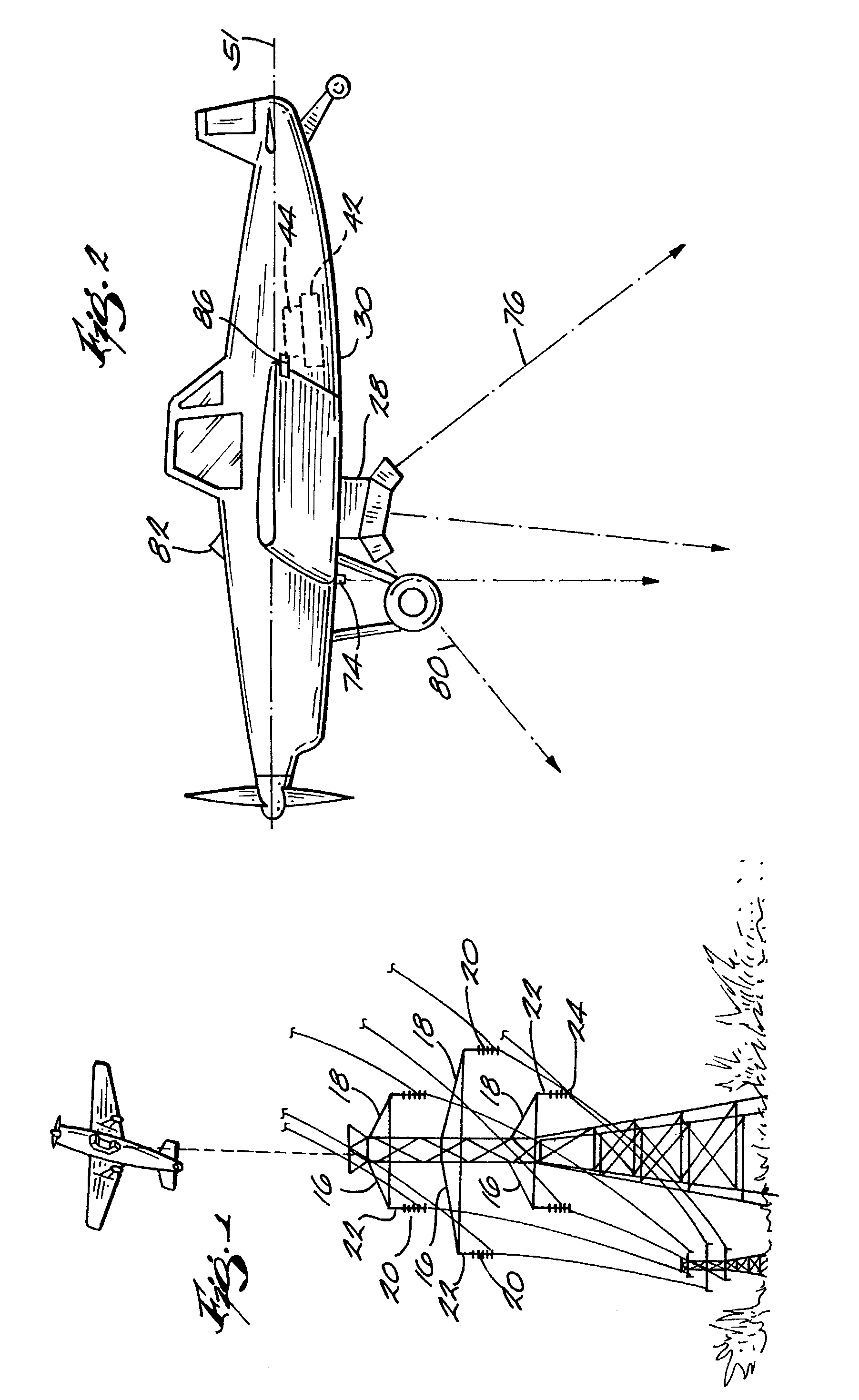
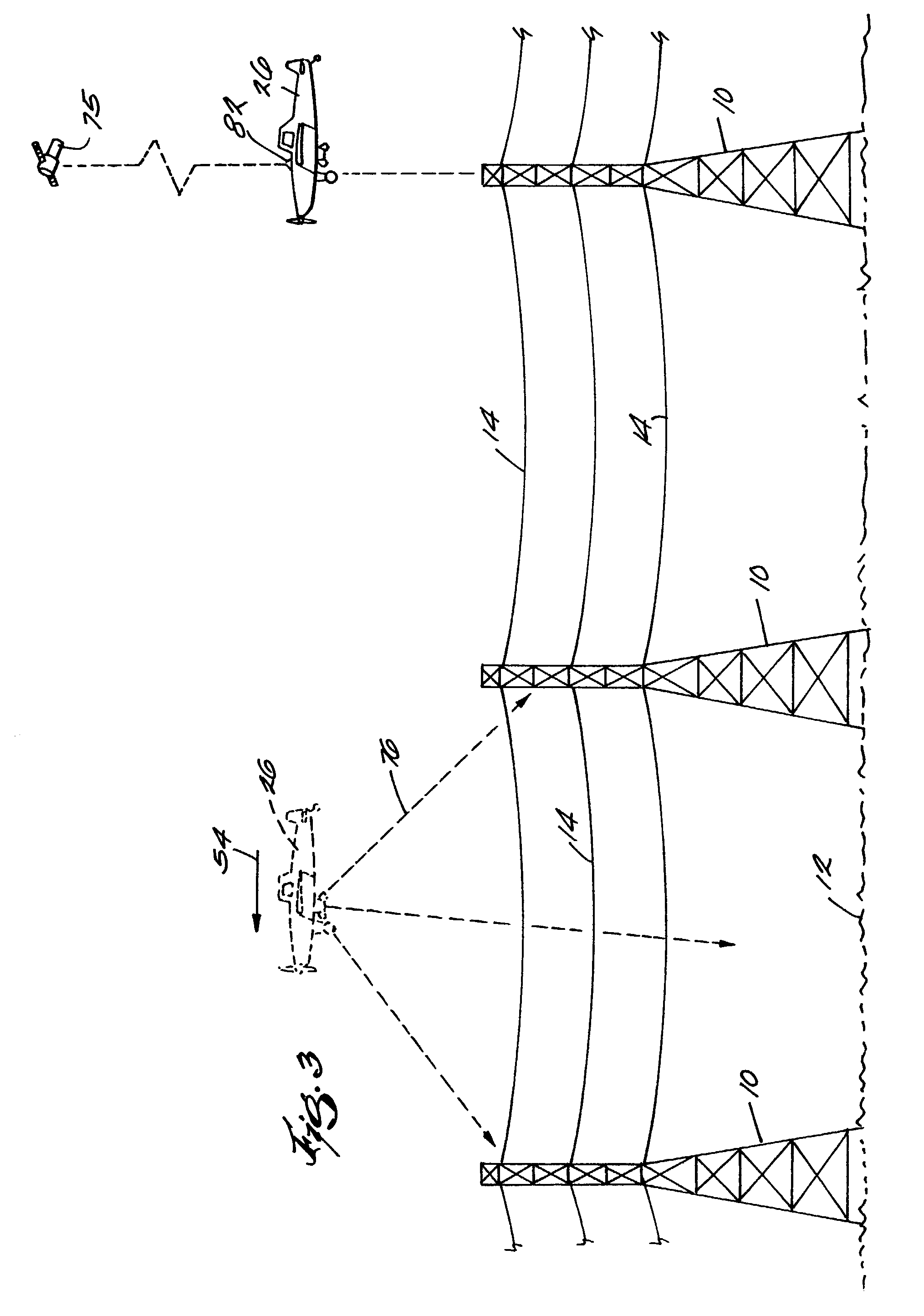
[0036]Electrical power is conveyed over transmission lines between power generating plants, field stations, states and the like. In their most basic configuration, these systems include towers 10, which in major part are uniformly spaced along the terrain 12 a desired distance, for example, two-tenths of a mile apart. Transmission cables or lines 14 are strung between the towers and suspended above the terrain. The towers can be of various heights as measured from the surface of the terrain, for example from 80–120 feet high. Transmission cables are supported at the tower structures by a combination of a laterally extending arm, or arms, 16 and 18. Insulators 20 are connected to the arms 16 and 18 with associated hardware 22 and 24. The transmission cables are anchored at the towers, specifically at the insulators, by the hardware 22 and 24 and the insulators maintain the necessary spacing between cables to ensure electrical isolation. The insulators and related hardware connections...


PUM


Abstract

A system and apparatus for acquiring images of electric transmission line tower structures, equipment attached to said tower structures, and transmission lines suspended from said towers. The system uses a fixed wing aircraft and an arrangement of at least one still camera, means for detecting a tower structure, a data storage unit, and a central processing unit containing operational software. The central processing unit is connected to the camera, the means for detecting a tower structure, and the storage unit. The detection means is a laser altimeter or a combination of preset longitude / latitude coordinates for tower locations and a GPS unit which supplies continuous longitude / latitude coordinates for the aircraft location for comparison to those preset coordinates. The aircraft is flown along the transmission line at a predetermined altitude above the tops of said towers (60–100 feet). The still camera points rearwardly relative to the line of flight of the aircraft and take a picture from between two adjacent towers and along an exposure line directed downwardly at an angle to the line of flight, 30–60 degrees and preferably 45 degrees. The detecting means transmits a signal to the central processing indicative of the presence of a tower to be photographed. The central processing unit calculates the time delay necessary for said aircraft to fly past the tower to a predetermined exposure point located between the tower to be photographed and the next tower in said transmission line after the tower to be photographed. The still camera is activated at the exposure point to acquire an image of the tower structure. The data corresponding to the acquired image is transmitted to a data storage unit for later retrieval and examination to identify defects in the tower or the equipment or transmission lines suspended form the tower. The system is reset to continue acquiring images along the transmission lines. The system is also provided with a video capability to film the towers and transmission lines and the line right-of-way.

Description

CROSS REFERENCE TO RELATED APPLICATIONS[0001]This application is a continuation of U.S. application Ser. No. 10 / 072,312, filed Feb. 8, 2002, which is a continuation of application Ser. No. 09 / 883,103, filed Jun. 15, 2001 and claims the benefit of the filing date of earlier filed provisional Application Ser. No. 60 / 211,742 filed Jun. 15, 2000 and entitled “Airborne Inventory and Inspection System.”TECHNICAL FIELD[0002]This invention relates to an airborne inventory and inspection system designed to obtain high resolution images of electric transmission power lines, the power line right-of-way and the support structure towers, along with a record of the respective location of the power line towers, which system is an improvement over current accepted systems and can be performed at a cost that makes use of this system more cost effective than alternatives available to the electrical power transmission industry.BACKGROUND OF THE INVENTION[0003]The electrical power industry has a recogn...

Claims


Application Information

Patent Timeline
Patent Type & Authority Patents(United States)
IPC IPC(8): H04N7/18
CPCG01C11/02H04N7/181G01S17/023G01S17/86
Inventor LOEWEN, JOHNREIMER, MARK
Owner POWER VIEW COMPANY L L C
Why Eureka
Try Eureka