Spool filled with multiple elongated elements wound closely together

a technology of elongated elements and spools, applied in the field of spools, can solve the problems of inability to meet the requirements of elongated elements, so as to avoid wrinkles in the final product, minimize unwinding problems, and minimize sags

Inactive Publication Date: 2007-03-06
NV BEKAERT SA
View PDF10 Cites 20 Cited by
  • Summary
  • Abstract
  • Description
  • Claims
  • Application Information

AI Technical Summary

Benefits of technology

[0016]It is another object of the present invention to minimize unwinding problems.
[0017]It is yet another object of the present invention to minimize sags during the unwinding of the plurality of elongated elements.
[0018]It is still another object of the present invention to avoid wrinkles in the ultimate product.
[0024]According to a second aspect of the present invention, there is provided a method of minimizing sags when unwinding multiple elongated elements from one single spool. The method comprises the following steps:
[0029]The common pulley preferably has a flat groove and most preferably the width of this groove is somewhat greater than the sum of the diameters of the multiple elongated elements. This gives the best results with respect to minimizing the distance s while still avoiding the entanglement between two neighboring elongated elements.

Problems solved by technology

A drawback of such a system is that it takes a lot of time to replace the empty spools by filled spools.
However, the simultaneous unwinding of a plurality of elongated elements from such a single spool, may cause difficulties and the subsequent parallel processing of the plurality of elongated elements may lead to an unacceptable degree of fractures and processability problems.
The unwinding difficulties and the processability problems and fractures during the subsequent treatment may be due to a variation in diameter of the elongated elements during their winding, or may be due to the fact that elongated elements become entangled during their winding, or may be due to the fact that the elongated elements, although wound at the same time on the same spool, take different lengths on the spool.
Other difficulties during the unwinding operations are due to different tensions in the individual elongated elements during the winding operation.
Despite these solutions problems are still experienced in determined circumstances when unwinding the plurality of elongated elements at the same time.
More particularly, when unwinding, some of the elongated elements show unacceptable large sags.
These sags may lead to entanglement with the neighboring elements or to wear or pollution of the sagged elements when these elements drag over the floor of the unwinding shop.
Still another problem is that the ultimate product, e.g. a rubber strip with the elongated elements may show some unacceptable wrinkles.

Method used


Image

  • Spool filled with multiple elongated elements wound closely together
  • Spool filled with multiple elongated elements wound closely together
  • Spool filled with multiple elongated elements wound closely together

Examples


first embodiment

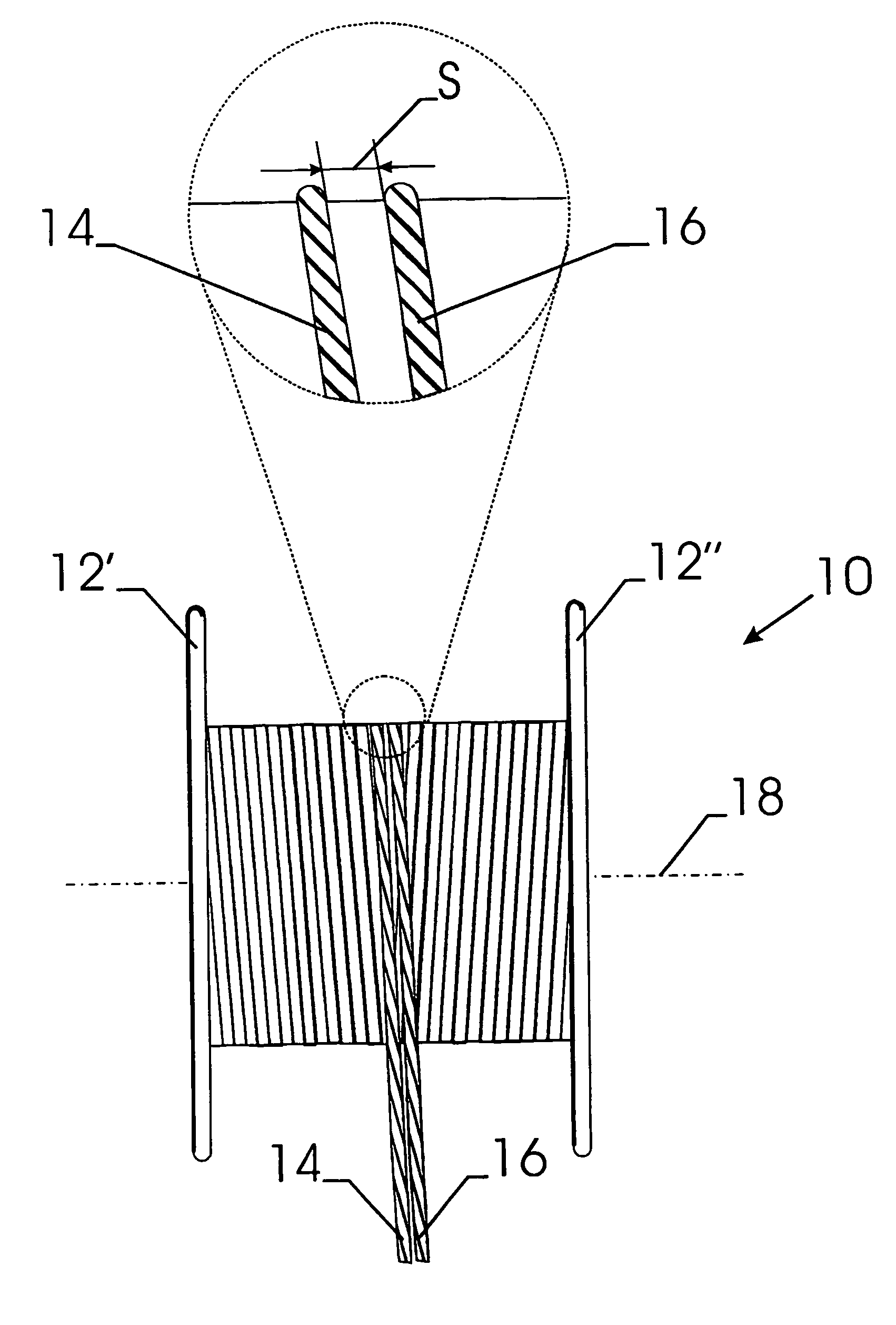
[0034]FIG. 1 shows a spool 10 according to the first aspect of the present invention. The spool 10 is provided with two flanges 12′ and 12″. Two steel cords 14 and 16, both twisted in S-direction, are wound in parallel and adjacent to each other on spool 10. The distance s, as measured along a line parallel to the axis 18 of spool 10, is less than 5 mm.

second embodiment

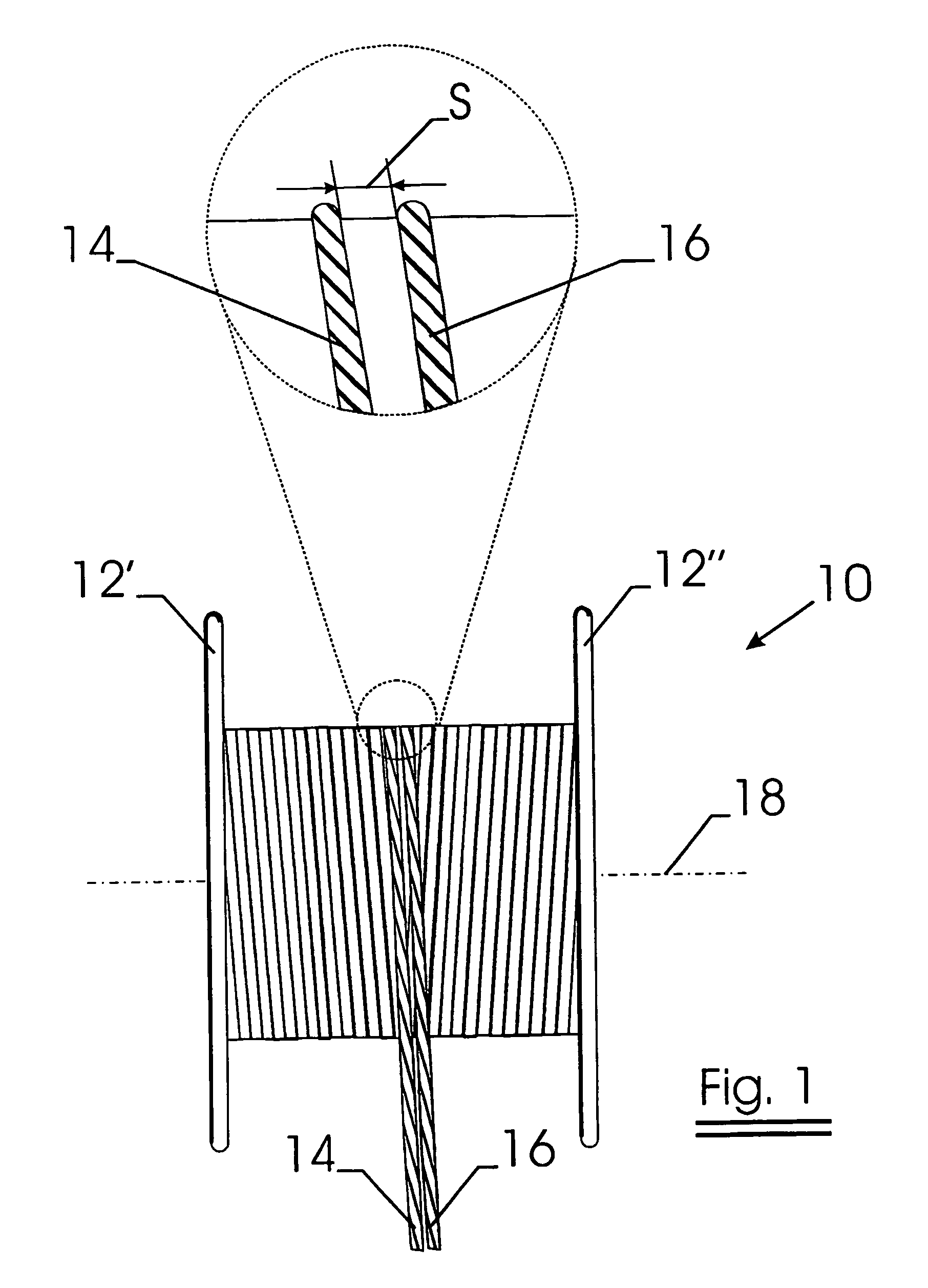
[0035]FIG. 2 shows a spool 10 according to a particular and second embodiment of the first aspect of the present invention. The spool 10 is provided with two flanges 12′ and 12″. A steel cord 14, twisted in S-direction, and a steel cord 16, twisted in Z-direction, are wound in parallel and adjacent to each other on spool 10. The distance s, as measured along a line parallel to the axis 18 of spool 10, is less than 5 mm. When using spools according to this particular embodiment of the invention on a creel in the field of rubber tires, an S-cord and a Z-cord will lie, one adjacent to the other in a composite ply rubber-steel cord. If all the spools on the creel will be spools according to the invention, there will be an equal number of S-cords and Z-cords on average over the whole composite rubber-steel cord ply. S-cords will alternate on average with Z-cords over the whole composite ply. In such a configuration it is likely that any residual torsions present on S-cords may compensate...


PUM


Abstract

A spool filled with two or more elongated elements such as steel cords wound in parallel and in several windings upon the spool. The distances between two neighboring elongated elements, as measured along a line parallel to the axis of the spool, is not more than 10 mm along 90% of the length of each elongated element.

Description

FIELD OF THE INVENTION[0001]The present invention relates to a spool filled with two or more elongated elements wound in parallel and in several windings upon the spool. The present invention also relates to a method of providing such a spool. The terms ‘elongated elements’ refer to elements the longitudinal dimension of which is more than hundred times larger than the cross-sectional dimensions. Common examples of elongated elements are round or flat steel wires, steel cords, textile yarns, copper strands, . . .BACKGROUND OF THE INVENTION[0002]Assemblies and apparatus for winding a plurality of elongated elements such as wires, cables or cords on one single spool are known in the art.[0003]As a matter of example, when manufacturing composites of rubber with steel cord, such as tires, the steel cords are very often drawn from a creel, which comprises a large number of spools, e.g. 20 to 150 spools in some embodiments and e.g. 500 to 1000 spools in other embodiments. The great number...

Claims


Application Information

Patent Timeline
Patent Type & Authority Patents(United States)
IPC IPC(8): B65H55/04B65H54/02B65H57/14B65H57/16
CPCB65H55/005B65H2701/35B65H55/04
Inventor MULLEBROUCK, RIKSABBE, LUCVANNESTE, STIJN
Owner NV BEKAERT SA
Why Eureka
Try Eureka