Metal/plastic insert molded sill plate fastener

a technology of metal/plastic insert and fastener, which is applied in the direction of threaded fasteners, screwing, couplings, etc., can solve the problems of inability of the fastener to compensate, the all metal body of the fastener itself, and the inability of the commonly used fastener to accommodate the slight rotation of the assembled joint. achieve the effect of improving the retention capacity

Active Publication Date: 2007-03-06
NEWFREY
View PDF58 Cites 24 Cited by
  • Summary
  • Abstract
  • Description
  • Claims
  • Application Information

AI Technical Summary

Benefits of technology

[0005]The anti-rotation feature is provided in the form of a generally V-shaped neck which mates with a similarly formed slot in an upper surface of a dog-house formed in the accessory joined to the vehicle. The anti-rotation feature permits a small degree of rotation of the apparatus to allow for fit-up but precludes further rotation. Each of the flexible wings also optionally includes an additional raised portion for improving the retention capability of each of the flexible wings. The support legs also provide at distal ends a protective guard feature such that the elastomeric material of the molded fastener body contacts the vehicle surface first to prevent potential damage between the fastener and the vehicle. Each of the protective guards also includes a tapered end feature to help align the fastener upon assembly.

Problems solved by technology

A drawback of commonly used fasteners is the inability of the fastener to compensate for misalignment between the fastener location and the aperture in the automobile.
A further drawback is the inability of commonly used fasteners to accommodate slight rotation of the assembled joint in order to compensate for further misalignment between the fastener and the aperture of the automobile.
Another drawback of some existing designs for fasteners is the all metal body of the fastener itself.
An all-metal fastener can result in corrosion between the metal contact surfaces between the fastener and the automobile as well as causing damage to the area of the aperture of the automobile upon insertion of the fastener or removal of the fastener.

Method used


Image

  • Metal/plastic insert molded sill plate fastener
  • Metal/plastic insert molded sill plate fastener
  • Metal/plastic insert molded sill plate fastener

Examples


Embodiment Construction

[0016]The following description of the preferred embodiment(s) is merely exemplary in nature and is in no way intended to limit the invention, its application, or uses.

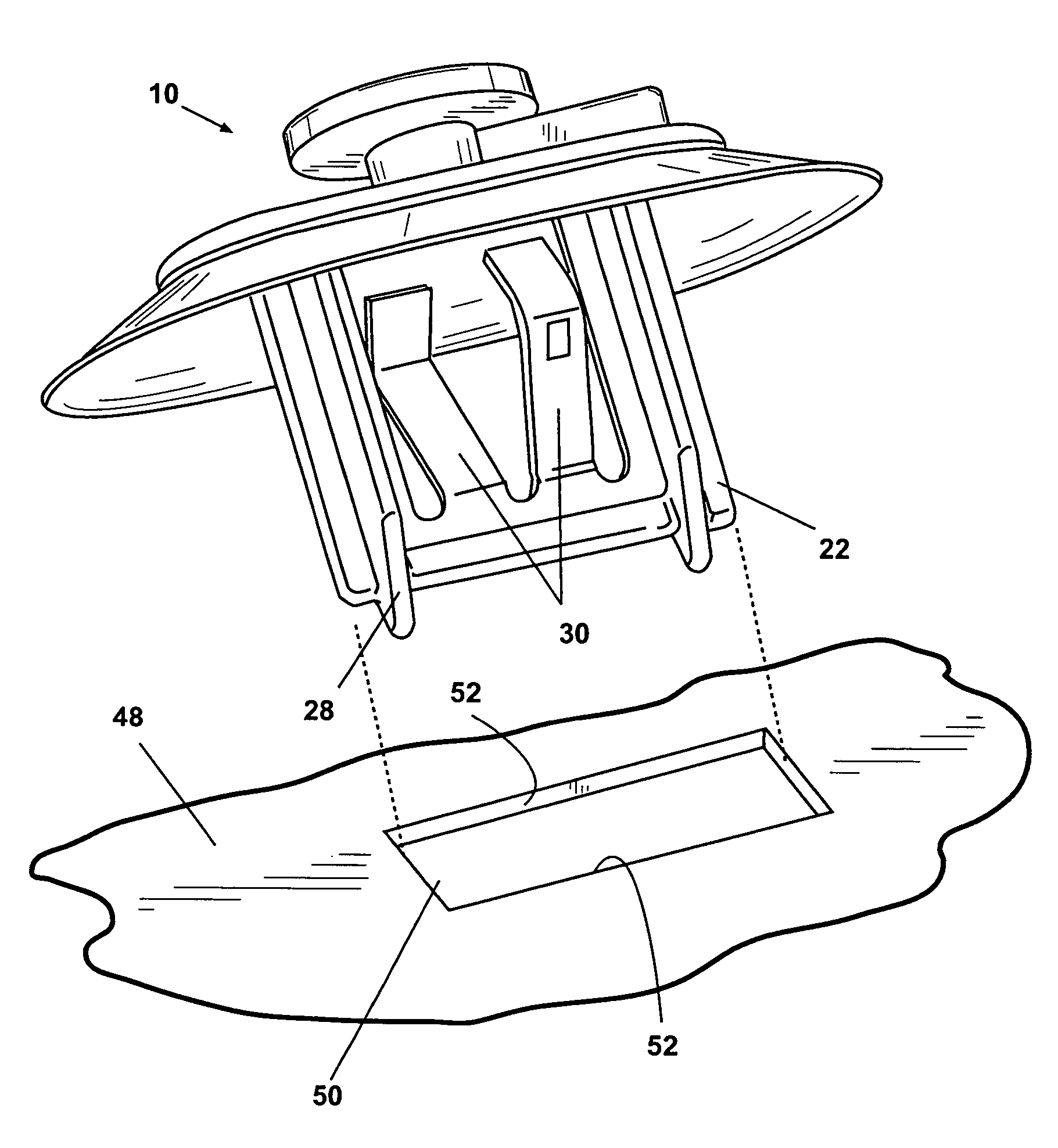
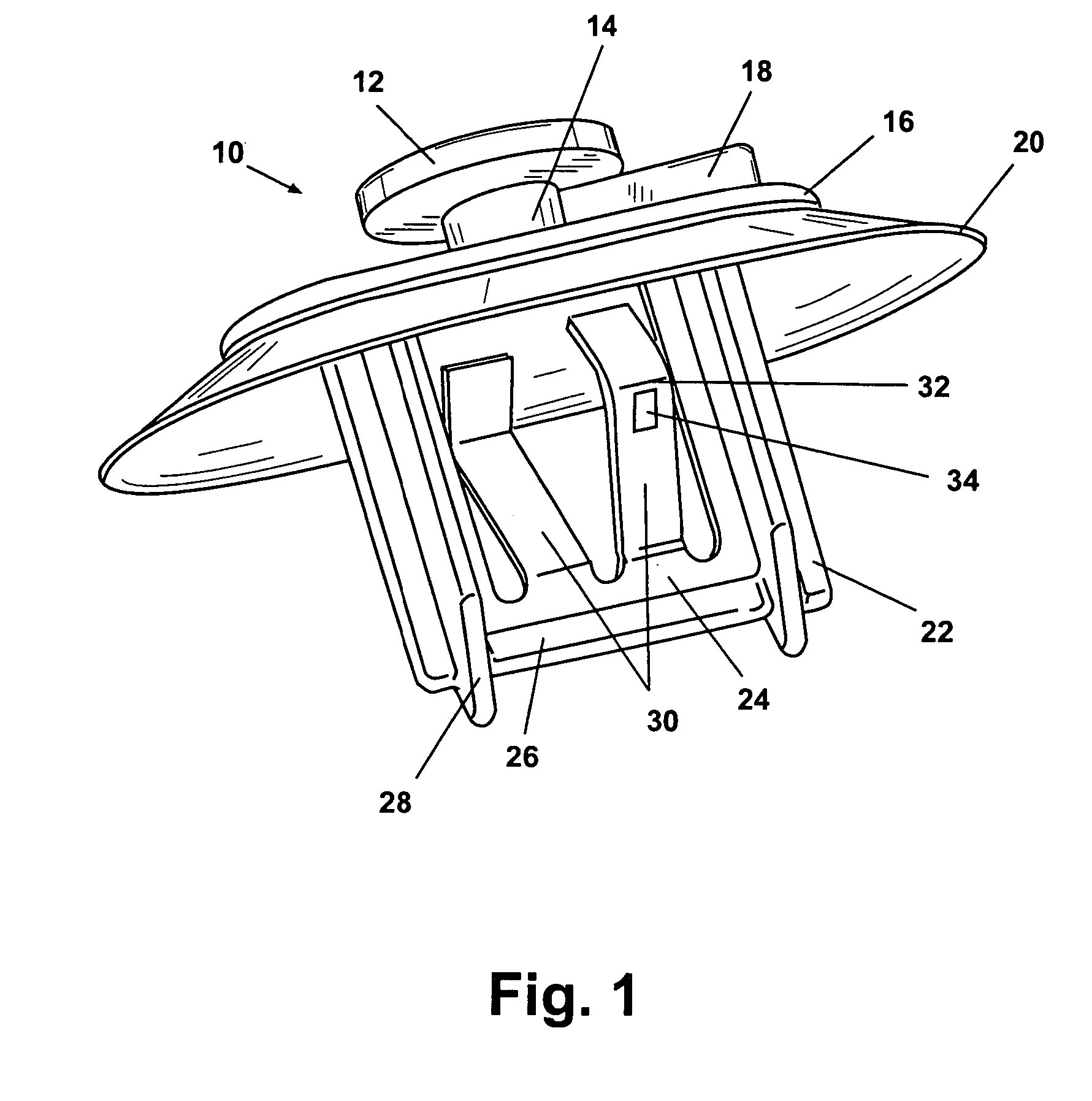
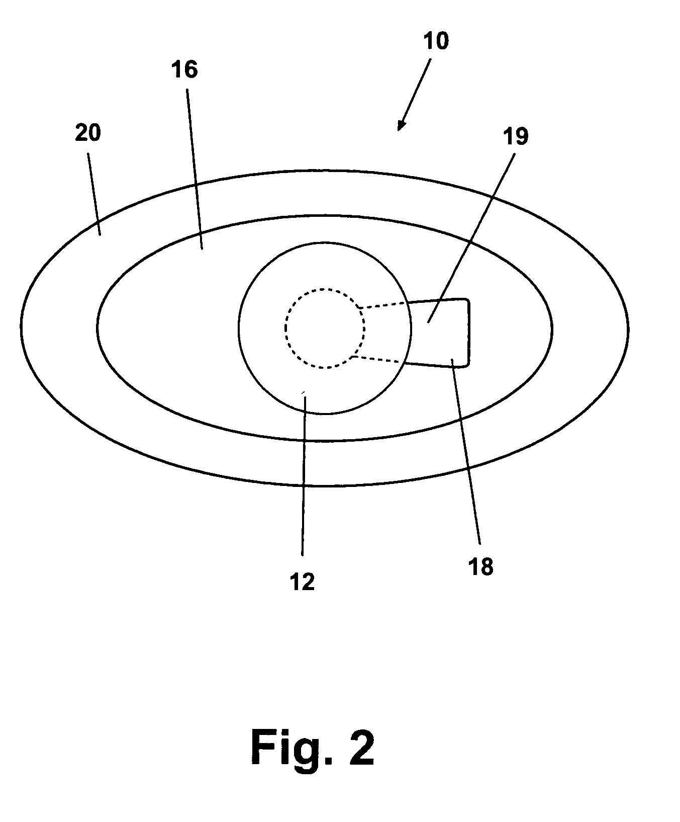
[0017]According to the preferred embodiment of the present invention, a fastener 10 includes a circular head 12 molded to a neck region 14. The neck region is co-molded to a top surface 16. An anti-rotation rib 18 which is formed in a general V-shaped configuration having its apex joined to neck region 14 is co-molded between neck region 14 and top surface 16. A flexible skirt 20 having a generally oval shape is co-molded to top surface 16 and extends generally downward and at an angle away from top surface 16. The top surface 16 is a generally planar portion of fastener 10 and also forms one of the surfaces for joining fastener 10 to a dog-house assembly which will be described in further detail in reference to FIGS. 3 and 4.

[0018]A pair of angled support legs 22 extend perpendicularly from an undersurface of the fle...


PUM


Abstract

A fastener for joining trim pieces to a motor vehicle includes a metal insert molded into an elastomeric body of a fastener. An anti-rotational rib prevents excessive rotation of the fastener after installation. Oppositely extending flexible wings of the metal insert are spaced from each other to allow full deflection upon insert of the fastener without interference between the flexible wings. Protective guards formed at distal ends of a pair of support legs provide improved insertion alignment for the fastener as well as protection between the fastener and metal surfaces of the vehicle. In another embodiment of the present invention, a dog house assembly is provided having aperture and slots mating with the installation features of the sill plate fastener. In still another embodiment, a method for installing a sill plate molding into a vehicle using a fastener of the present invention is provided.

Description

FIELD OF THE INVENTION[0001]The present invention relates generally to fasteners and more specifically to a fastener design for joining trim pieces to the interior surfaces of automobiles.BACKGROUND OF THE INVENTION[0002]For automotive applications, fasteners are used to join trim pieces to sections or metal body portions of the automobile. The requirements for these fasteners are that they be insertable into apertures of the automobile and meet requirements to both retain the insert as well as provide a minimum pullout retention force such that the insert can be removed without damaging the insert. Common fastener designs include directly opposed flexible wings which deflect inwardly upon insertion of the fastener and expand by spring force to hold the fastener within a rectangular slot in the automobile. A drawback of commonly used fasteners is the inability of the fastener to compensate for misalignment between the fastener location and the aperture in the automobile. A further d...

Claims


Application Information

Patent Timeline
Patent Type & Authority Patents(United States)
IPC IPC(8): B25G3/36E04G7/00F16B5/02F16B19/00B60R13/02
CPCB60R13/0206Y10T24/309Y10T403/7123Y10T403/7176Y10T24/42Y10S411/908Y10T403/581Y10T24/45995Y10S411/913Y10S411/903Y10T403/606F16B2200/69
Inventor BENEDETTI, STEVEN MNESSEL, ROSALIND A
Owner NEWFREY
Why Eureka
Try Eureka