Panel grip with modified seam

a panel grip and seam technology, applied in the direction of golf clubs, steering devices, cycle equipment, etc., can solve the problems of difficult to accurately align the adjoining side edges of the strip, limited in its ability to accommodate multiple color schemes, labor-intensive fabrication, etc., and achieve the effect of ensuring the same resistance to shock

Active Publication Date: 2007-03-06
WINN INC
View PDF124 Cites 80 Cited by
  • Summary
  • Abstract
  • Description
  • Claims
  • Application Information

AI Technical Summary

Benefits of technology

[0011]Embodiments of the golf club grip of the present invention overcome the aforementioned disadvantages of existing spirally wrapped grips and the single panel grips while providing the same resistance to shock afforded by such grips, as well as providing tackiness. Desirably, a structurally integral grip is formed from at least an outer panel and an inner panel coupled together in an offset mating relationship.
[0018]Embodiments of the present invention may be manufactured at considerably less cost than existing spirally wrapped grips since it eliminates the intensive labor of spirally wrapping a strip around an underlisting sleeve within specific pressure parameters. Additionally, embodiments will not twist either during manufacture or after it is adhered to an underlisting sleeve. My new grip desirably has an appearance similar to conventional molded rubber grips so as to appeal to professional golfers and low-handicap amateurs, and also provides a greater area for the application of decorative designs. Further, embodiments of the present invention can also accommodate multiple color combinations, thus appealing to golfers and college programs who wish to display their school colors while playing the sport they love. Embodiments of the present invention are also cheaper to manufacture than previous panel designs because the additional step of skiving the side edges is eliminated. Embodiments of the present invention are very easy to install.

Problems solved by technology

While such grips have proven satisfactory in reducing impact shock, the fabrication is labor intensive, particularly since the strip must be wrapped manually about the underlisting sleeve within specific pressure parameters.
Additionally, it is difficult to accurately align the adjoining side edges of the strip as such strip is being spiraling wrapped about the underlisting sleeve.
These wrapped grips can become twisted during the wrapping process, allow for only limited display of decorative designs, and allow for only a limited placement of colors.
While this design removes the twisting problems associated with the wrapping process and offers more area to display decorative designs, it is limited in its ability to accommodate multiple color schemes which are so popular in today's modern world of golf.
While such grips have continued to prove satisfactory in reducing impact shock, the fabrication has our remained intensive, particularly since the panel is skived along the side edges so that the seams along the intersection of the side edges remain relatively smooth.
Additionally, it is difficult to easily and efficiently skive various patterns in the single panel grips of the previous designs.
The panel grips therefore allow for only limited display of decorative designs and limited placement of colors.

Method used


Image

  • Panel grip with modified seam
  • Panel grip with modified seam
  • Panel grip with modified seam

Examples


Embodiment Construction

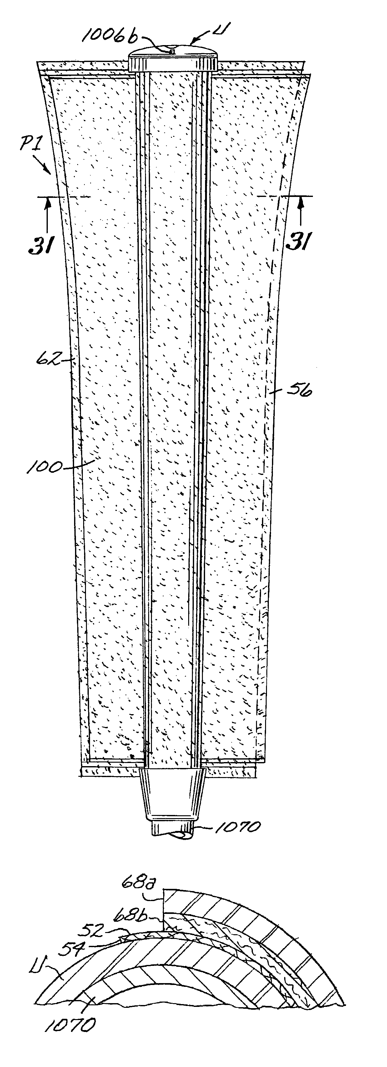
[0093]Referring to the drawings, in FIG. 69, a panel grip G1 embodying the present invention is shown attached the shaft SC of a golf club C. In FIG. 70, a putter grip PG2 embodying the present invention is shown attached to the shaft SP of a putter PC. Referring now to the remaining drawings, a preferred form of a grip includes a coupled multilayer panel formed of an outer multilayered panel and an inner strength panel which is then wrapped about and coupled to a resilient underlisting sleeve of a conventional construction. Throughout the application, the term top is used to refer to that which is closest to the bottom end of the club opposite the club head, i.e. the end closest to the golfer if that golfer were to be swinging or stroking the club. Similarly, the term bottom is used to define that which is furthest from the butt end of the club.

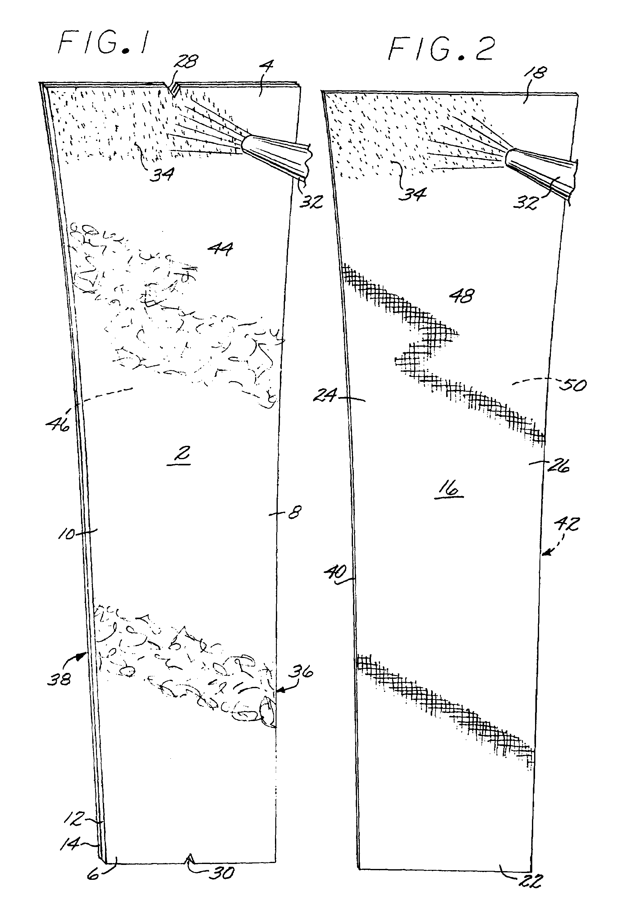
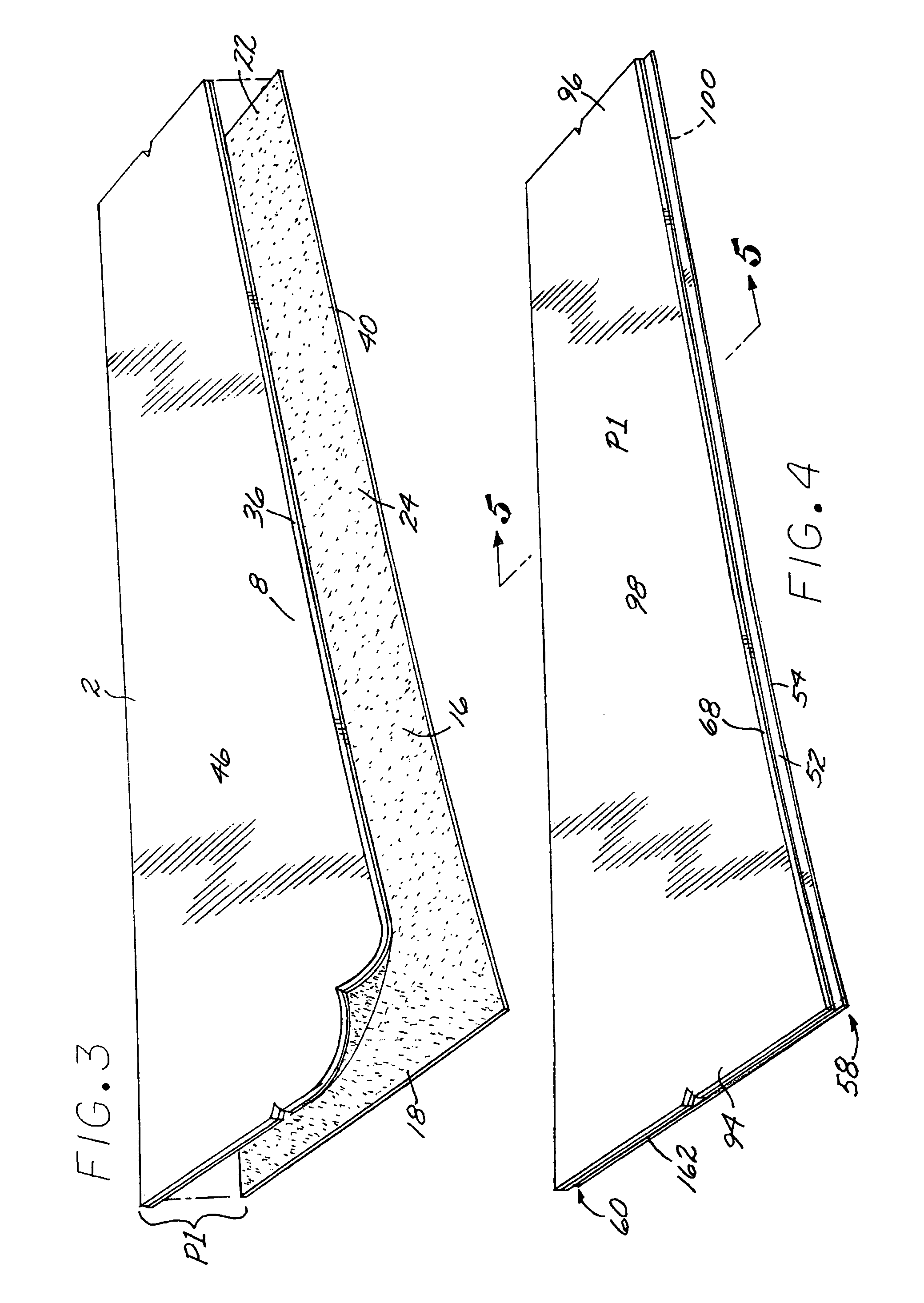
[0094]FIG. 1 shows an outer multilayered panel 2 for use in constructing a coupled multilayered panel P1 (FIG. 4). Outer panel 2 is prefera...


PUM

PropertyMeasurementUnit
thicknessaaaaaaaaaa
thicknessaaaaaaaaaa
surface areaaaaaaaaaaa

Abstract

A grip for the handle of a golf club having at least one panel with a modified seam that is wrapped about an underlisting sleeve. The edges of the panels are coupled together with three attachment interfaces. The grip reduces impact shock and provides a feeling of tackiness in the manner of a spirally wrapped polyurethane-felt grip while allowing the use of multiple color panels and inserts and easy installation onto a golf club shaft.

Description

BACKGROUND OF THE INVENTION[0001]1. Field of the Invention[0002]This application relates to an improved grip for shafts. In particular, this application relates to an improved grip for the shafts of golf clubs.[0003]2. Incorporation by Reference[0004]This application hereby incorporates by reference, in their entirety, U.S. Pat. Nos. 6,244,975; 6,627,027; 6,695,713; 6,843,732; and 6,857,971.[0005]3. Description of the Related Art[0006]Applicant has previously developed resilient grips which successfully reduce impact shock to the muscle and arm joints of the users of golf clubs and also provide a feeling of tackiness between the player's hands and the grip. See, for example, U.S. Pat. No. 5,797,813 granted to Applicant on Aug. 25, 1998, U.S. Pat. No. 6,843,732 granted to Applicant on Jan. 18, 2005, and U.S. Pat. No. 6,857,971 granted to Applicant on Feb. 22, 2005.[0007]The earliest of these grips utilize a polyurethane-felt strip which is spirally wrapped around an underlisting slee...

Claims


Application Information

Patent Timeline
Patent Type & Authority Patents(United States)
IPC IPC(8): A63B53/14
CPCB62K21/26A63B53/14A63B59/0029B32B7/02B32B7/12A63B49/08A45B9/02A63B59/0014A63B59/0033A63B59/0092A63B2243/0041B32B2250/02B32B2255/26B32B2307/744B32B2451/00A63B60/10A63B60/16A63B60/06A63B60/54A63B2102/22A63B60/08A63B60/14A63B60/00
Inventor HUANG, BEN
Owner WINN INC
Why Eureka
Try Eureka