Methods and apparatus for promoting fusion of vertebrae

a vertebral fusion and fusion technology, applied in the field of vertebral fusion methods and apparatuses, can solve the problems of preventing excessive subsidence, reducing the fusion rate of vertebrae, so as to promote optimal fusion at the graft, minimize stress shielding as well as excessive subsidence

Inactive Publication Date: 2007-03-06
DINH DZUNG H +1
View PDF51 Cites 87 Cited by
  • Summary
  • Abstract
  • Description
  • Claims
  • Application Information

AI Technical Summary

Benefits of technology

[0013]It has been found that the above and related objects of the present invention are obtained by the use of slidably interconnected plates that fixate vertebrae to each other and provide for a predetermined amount of subsidence at the fusion site. This predetermined subsidence increases bone to bone contact at the graft, which promotes fusion without having excessive compression of the two vertebrae onto the graft. The predetermined subsidence is achieved by the placement of a plate spacer between each of two interconnecting plates when the plates are attached to the vertebrae. The plate spacer has a height equal to the amount of subsidence desired. After affixing the plates to the vertebrae, the plate spacer is removed, leaving a space between the plates, which allows the vertebrae to subside by a distance equal to the height of the plate spacer.
[0015]A preferred embodiment of these apparatuses comprises a first plate mountable to the first vertebra, and a second plate mountable to the second vertebra. The first plate comprises integral means for slidably interconnecting with the second plate, the sliding occurring parallel to the long axis of the spinal column. The means for slidably interconnecting the first and second plates prevents rotational and transverse movement of the first vertebra relative to the second vertebra.
[0019]In still other preferred embodiments, the invention is directed to apparatuses for promoting fusion of a first vertebra and a second vertebra in a spinal column at a graft between the first vertebra and the second vertebra. The apparatuses comprise a first plate mountable to the first vertebra, a second plate mountable to the second vertebra, and a removable plate spacer suitable for placing between the first plate and the second plate, where the plate spacer comprises a height. In these embodiments, the first plate comprises an integral means for slidably interconnecting with the second plate, where the sliding occurs parallel to the long axis of the spinal column. This means prevents rotational and transverse movement of the first vertebra relative to the second vertebra. The apparatuses of these embodiments further comprise a means for limiting axial extension of the first plate with respect to the second plate.
[0021]In related embodiments, the invention is directed to apparatuses for promoting fusion of n adjacent vertebrae in a spinal column at grafts between each of the n vertebrae. The apparatuses comprise n plates, each plate mountable to one of each of the n vertebrae. Each plate also comprises integral means for slidably interconnecting with adjacent plate(s), where the sliding occurs parallel to the long axis of the spinal column. This means prevents rotational and transverse movement of each of the n vertebrae relative to each adjacent vertebra(e) of the n vertebra.

Problems solved by technology

However, the apparatuses can also lead to stress shielding, in which fusion of the vertebrae to the grafted bone is impeded or prevented entirely because the apparatus prevents adequate contact between the vertebra and the graft.
Resorption of the bone graft can exacerbate this problem.
Thus, while the apparatus in the '082 patent does not cause stress shielding, it also does not prevent excessive subsidence.

Method used


Image

  • Methods and apparatus for promoting fusion of vertebrae
  • Methods and apparatus for promoting fusion of vertebrae
  • Methods and apparatus for promoting fusion of vertebrae

Examples


Embodiment Construction

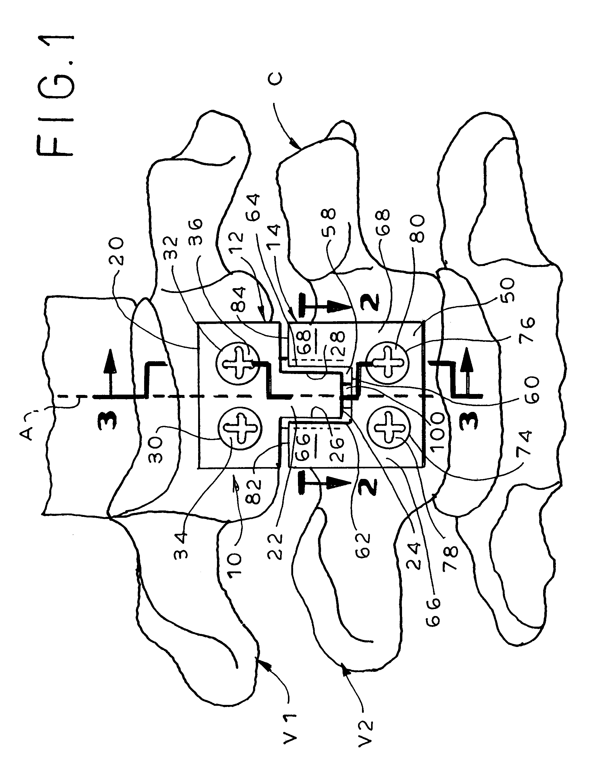
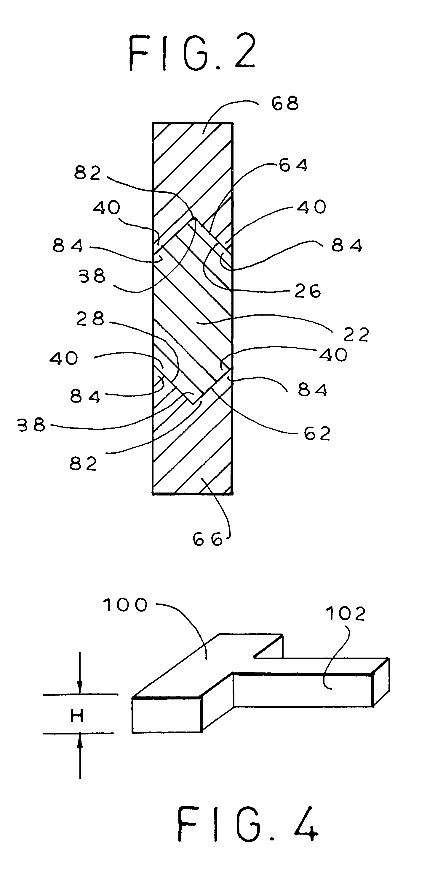
[0035]The present invention provides methods and apparatuses for stabilizing vertebrae while simultaneously minimizing stress shielding and excessive subsidence. To achieve this, apparatuses are utilized that have at least two separate members, one member being attached to each of the vertebrae. The members that are adjacent to each other can be interconnected to prevent rotational and transverse displacement of the two vertebrae in relation to each other. Additionally, the apparatuses preferably include plate spacer(s) of a preselected height that is placed between each two adjacent members when the members are attached to the vertebrae, such that the members are separated by the height of the plate spacer. After attachment of the members to the vertebrae, the plate spacer(s) is / are removed. This allows for subsidence of the each two adjacent vertebrae by a distance equal to the height of the plate spacer. Thus, stress shielding as well as excessive subsidence is minimized.

[0036]In...


PUM


Abstract

Methods and apparatuses for promoting fusion of vertebrae are provided. The apparatuses comprise interconnecting plates that fixate vertebrae to each other and provide for a predetermined amount of subsidence where the fusion occurs. Allowing for this predetermined amount of subsidence increases bone to bone contact at the graft, which promotes fusion without having excessive settling of the two vertebrae onto the graft. The predetermined amount of subsidence is achieved by the placement of a plate spacer between each of two interconnecting plates when the plates are attached to the vertebrae. The plate spacer has a height equal to the maximum amount of subsidence desired. After affixing the plates to the vertebrae, the plate spacer is removed, leaving a space between the plates, which allows the vertebrae to subside by a distance equal to the height of the plate spacer.

Description

CROSS-REFERENCE TO RELATED APPLICATION[0001]This application claims the benefit of U.S. Provisional Application 60 / 359,875, filed Feb. 25, 2002.BACKGROUND [0002](1) Field of the Invention[0003]The present invention relates to methods and apparatuses for stabilizing vertebrae when fusing the vertebrae.[0004](2) Description of the Related Art[0005]Fusion of vertebrae is often necessary to relieve debilitating pain or correct a deformity. When vertebrae are fused, e.g., with bone grafts, graft extenders, or interbody spacers such as interbody cages or boxes (collectively termed “grafts” herein), it is desirable to stabilize the fused vertebrae using an apparatus such as a plate to fixate one cervical vertebra to another to promote fusion across motion segments.[0006]There are various known apparatuses useful for stabilizing vertebrae when the vertebrae are fused. See, e.g. U.S. Pat. Nos. 4,743,260; 5,603,703; 5,458,641; 5,827,328; and 6,080,193.[0007]The known apparatuses are generally...

Claims


Application Information

Patent Timeline
Patent Type & Authority Patents(United States)
IPC IPC(8): A61B17/58A61B17/70A61B17/80A61F2/44
CPCA61B17/7059A61B17/8023A61B17/8004
Inventor DINH, DZUNG H.VILLARRAGA, MARTA L.
Owner DINH DZUNG H
Why Eureka
Try Eureka