
Low cost indoor grease trap

a grease trap and low cost technology, applied in water cleaning, liquid displacement, separation processes, etc., can solve the problems of clogging of sewer system lines, messy and time-consuming servicing, and difficulty in servicing existing devices

Active Publication Date: 2007-03-06
THERMACO INC
View PDF41 Cites 29 Cited by
  • Summary
  • Abstract
  • Description
  • Claims
  • Application Information

AI Technical Summary

Benefits of technology

[0006]The present invention fulfills one or more of these needs in the art by providing an oil / grease removal assembly including a container having a bottom, a top, a sidewall, an input end and discharge end. An inlet at the input end is adapted to receive effluent from a sink drain, and a drain connection at the discharge end spaced above the bottom and below the top defines a static water level for liquid in the container. A baffle in the container extends downwardly near the discharge end to a level below the static water level to allow water to flow below the baffle from the inlet to the drain connection but retaining oil / grease floating on the water upstream of the baffle. A means is provided for intermittently raising the liquid level in the container above the static water level. A port in the container upstream of the baffle is at an elevation such that oil / grease floating on water in the container upstream of the baffle can flow from the container out through the port when the liquid level in the container is raised above the static water level.

Problems solved by technology

Sewer system lines can become clogged from the oil / grease waste materials put into the sewer system from food handling facilities.
The existing devices may be difficult to service and are very often permanently installed at facility sites.
Because many of the parts are coated with oil / grease, servicing can be messy and time consuming.
In addition, these systems tend to be expensive and represent a significant capital investment.

Method used


Image

  • Low cost indoor grease trap
  • Low cost indoor grease trap
  • Low cost indoor grease trap

Examples


Embodiment Construction

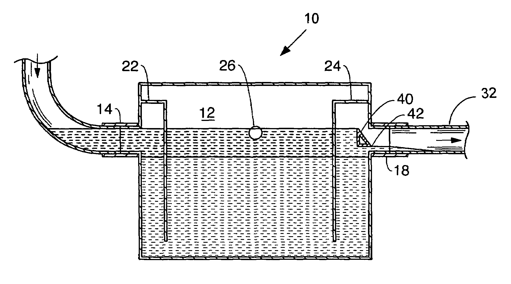
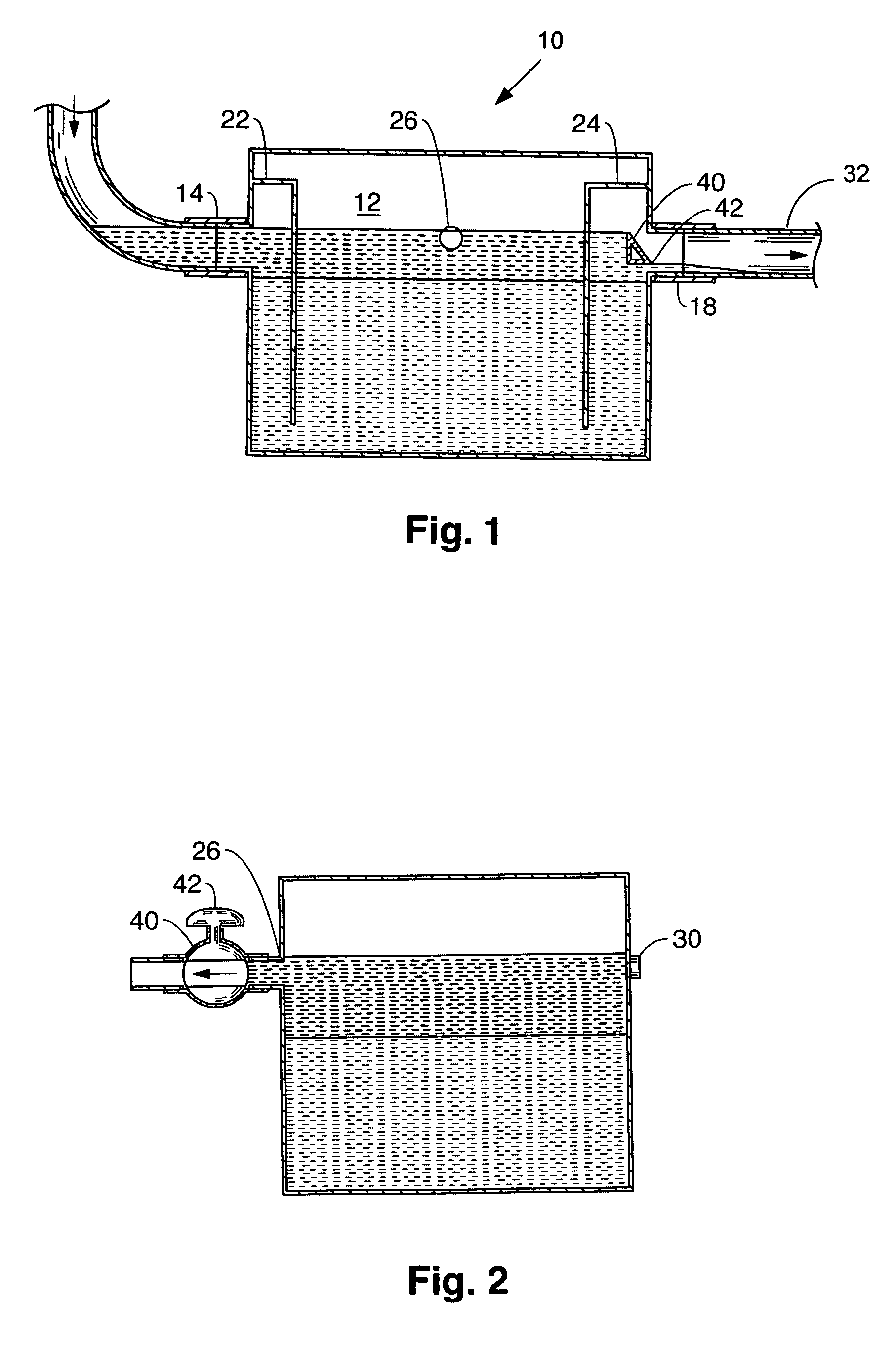
[0027]As seen in FIGS. 1 and 2, an indoor grease trap 10 is provided as a container 12 having a bottom, a top, two sidewalls and, an input end and a discharge end. An inlet 14 at the input end receives effluent from a kitchen sink or similar source of effluent containing primarily water and oil / grease. The system can also be used with other sources of effluent that have a heavier and a lighter component to separate the lighter component from heavier component to be passed downstream. The container is shown as a right parallelepiped, but other suitable shapes can be used.

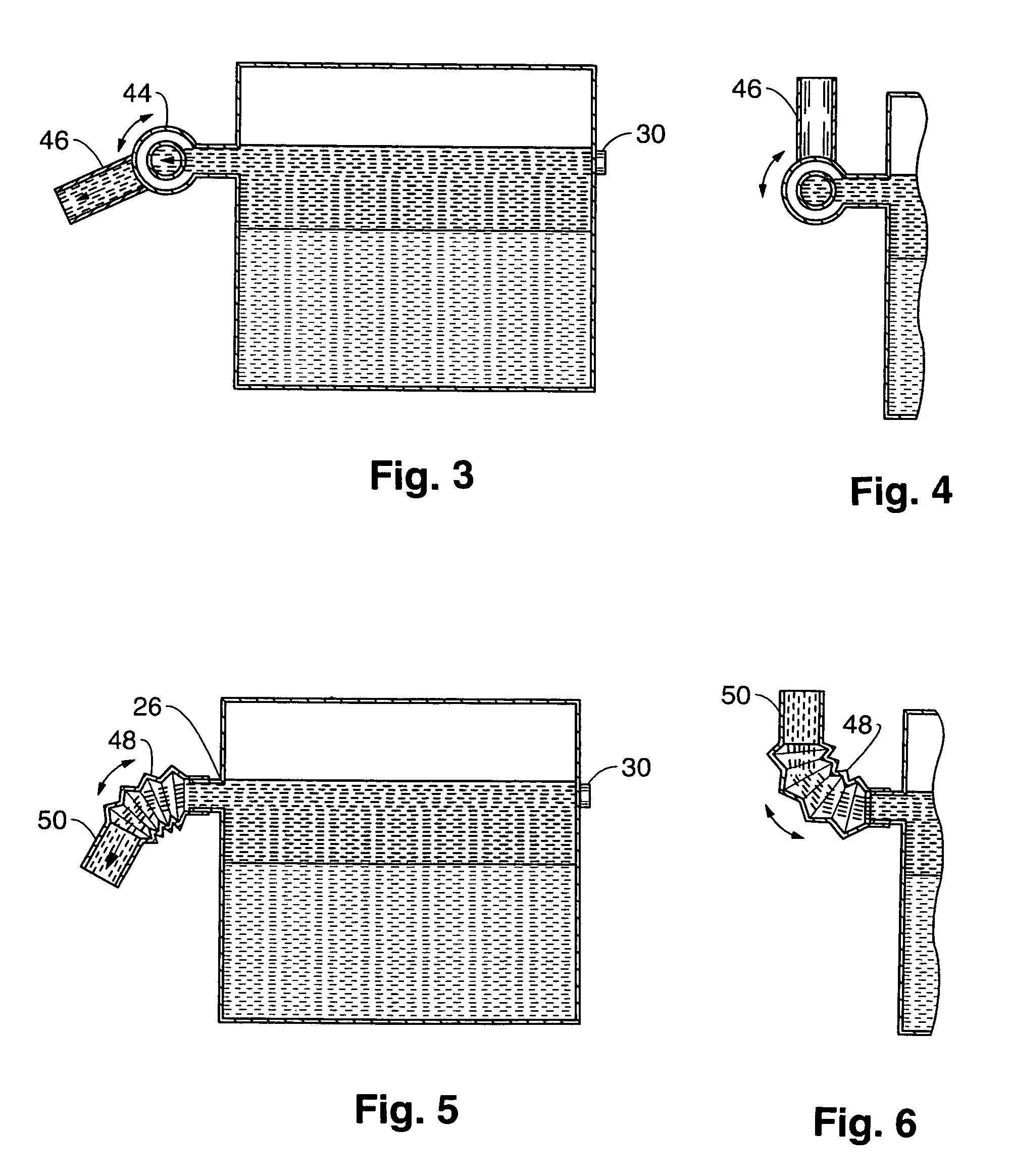
[0028]At the discharge end of the container is an outlet 18 connected to a sewer line 32. The outlet is located below the top and above the bottom of the container 12. As a drain, it defines the static water level in the container 12. Just upstream of the outlet 18 within the container 12 is a discharge baffle 24 which extends downwardly from at least as high as the highest expected liquid level, to a point in a lowe...


PUM

PropertyMeasurementUnit
angleaaaaaaaaaa
volumeaaaaaaaaaa
flexibleaaaaaaaaaa

Abstract

An oil / grease removal assembly includes a container having an inlet to receive effluent from a kitchen sink. A drain connection spaced above the container bottom defines a static water level for contained liquid and connects to a sewer. A baffle extends downwardly below the static water level so water can flow below the baffle to the drain, while retaining floating oil / grease. Means intermittently raise the liquid level in the container above the static water level. Floating oil / grease can flow out through a port when the liquid level in the container is raised above the static water level.

Description

BACKGROUND OF THE INVENTION[0001]This invention relates to a low cost assembly for the removal and recovery of fat, oil and / or grease (hereinafter referred to as oil / grease) found in effluent discharge of restaurants, food processing, or like facilities, or other circumstances involving mixtures of oil / grease to be recovered or removed.[0002]Oil / grease removal or recovery systems are well known. Sewer system lines can become clogged from the oil / grease waste materials put into the sewer system from food handling facilities. This has led more and more sewer authorities to implement fats, oils and grease control programs. These programs regulate food handling facilities and the manner in which they process oil / grease. The object of many of these programs is to ensure that food handling facilities remove as much of the oil / grease as possible from the effluent flow, thereby releasing only grey water, perhaps with solids, to the sewer system.[0003]One method recognized in the prior art o...

Claims


Application Information

Patent Timeline
Patent Type & Authority Patents(United States)
IPC IPC(8): B01D17/025
CPCB01D17/0214B01D17/0211
Inventor BATTEN, WILLIAM C.KEMP, CHARLESKYLES, BRUCE W.
Owner THERMACO INC
Learn More