Combining transmittance detection and chromatographic strip techniques for quantification of analyte in biological fluids

a technology of chromatographic strip and transmittance detection, which is applied in the direction of analytical using chemical indicators, laboratory glassware, instruments, etc., can solve the problems of complex test procedures, limited sensitivity of reflectance biosensors, and need special equipment, so as to simplify the test process and achieve good sensitivity , the effect of high sensitivity

Inactive Publication Date: 2007-03-06
QIAN SUYUE
View PDF10 Cites 72 Cited by
  • Summary
  • Abstract
  • Description
  • Claims
  • Application Information

AI Technical Summary

Benefits of technology

[0011]Reflectance biosensors have sensitivity limitations. Many clinical tests require an extremely high sensitivity that is far beyond the reflectance biosensor's capability. Then detection principles, such as transmittance, fluorescence, magnetic field, chemiluminescence, and electrochemistry have been widely used. However, these tests procedures are much more complicated, need special equipment, and require well trained technicians. Chromatography is a powerful technique for the separation of biomacromolecules using their specific biological activity or chemical nature. The separation media consists of a ligand attached to an insoluble, inert matrix. When the biological fluid passes through the chromatography media, the analyte will bind to the media while interferents and other proteins will be washed away by the biological fluid as wash. The capture of the analyte by chromatographic media simplifies the test process. When we combine these sensitive detections and simple analyte captures together, the test will have good sensitivity as well as simplicity.
[0013]In short, the invention furnishes enormous analytical advantages, including improved precision, expanded detection range, faster testing and most importantly easy use. The transmittance system provides a sensitive detecting capability, which the reflectance system does not. The chromatographic strip simplifies the procedures and achieves the simplicity and reliability as opaque membrane does. For these reasons, this new approach will bring great convenience for home users and small clinics.

Problems solved by technology

Reflectance biosensors have sensitivity limitations.
However, these tests procedures are much more complicated, need special equipment, and require well trained technicians.

Method used


Image

  • Combining transmittance detection and chromatographic strip techniques for quantification of analyte in biological fluids
  • Combining transmittance detection and chromatographic strip techniques for quantification of analyte in biological fluids
  • Combining transmittance detection and chromatographic strip techniques for quantification of analyte in biological fluids

Examples


examples

Test Strip used in the Experiment (One Detection Cell Only, FIG. 3)

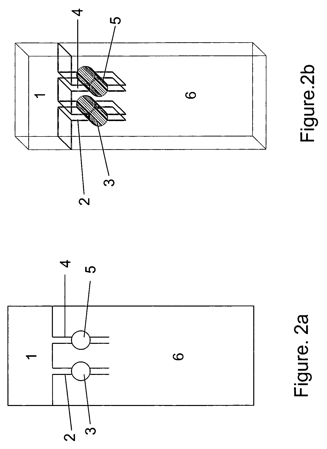
[0034]The dry strip has a dimension of 1.58×0.35×0.041 inch. Frame 15 of the strip is made with Mellinex plastic. The frame itself is 0.075 inches width each side. The detection cell, that is: capture zone 16 is 0.2×0.2×0.035 inch dimension. Both ends 12 and 13 of the cell are framed with porous plastic from Porex to hold the beads between, but permit fluid flowing through. Both front and back of the strip are glued with a 0.003 inches of Mylar transparent membrane to hold the beads in the detection cell and allow the light transmission through the detection cell. The absorbent pad fills the space of the strip 14 to absorbing fluid. Agarose beads covalently linked with the affinity reagent—boronic acid from Pierce are packed into the detection cell 16.

[0035]Experiment 1 (Quantitation of Glycated Hb) The samples from Aalto Scientific were used for this study. The glycated Hb values of used samples first were determine...

experiment 3 (detection of the amount of ghb by their peroxidase activity) alternative way to determine the amount of glycated hb and total hb is to measure their peroxidase activities.when glycated hb binds to the beads in the detection cell , the heme in glycated hb oxidizes or reduces the substrate and produces a visible color product.the product absorbs light at a selected wavelength.the samples with different levels of glycated hemoglobin were diluted with a sample buffer to 1 : 50 , 000.the 200 ul of dilution was added to the sample application well , and the strip was further washed with 200 ul of buffer washing away the non bound hb.200 ul of tmb membrane peroxidase substrate solution from kpl was applied to the sample well and as it flowed down a color product developed in the cell , which was proportional to the ghb bound to the beads (fig.6)

Experiment 3 (Detection of the Amount of GHb by their Peroxidase Activity) Alternative way to determine the amount of glycated Hb and total Hb is to measure their peroxidase activities. When glycated Hb binds to the beads in the detection cell, the heme in glycated Hb oxidizes or reduces the substrate and produces a visible color product. The product absorbs light at a selected wavelength. The samples with different levels of glycated hemoglobin were diluted with a sample buffer to 1:50,000. The 200 ul of dilution was added to the sample application well, and the strip was further washed with 200 ul of buffer washing away the non bound Hb. 200 ul of TMB membrane peroxidase substrate solution from KPL was applied to the sample well and as it flowed down a color product developed in the cell, which was proportional to the GHb bound to the beads (FIG. 6). The color intensity was determined same way as in experiment 1 and 2.

experiment 4 (detection of the amount of igg-hrp conjugates using chromatographic strip) a 1 : 2000 dilution (pbs) of igg-hrp conjugate (mouse igg-hrp from pierce) was prepared.5 , 10 , 15 , 20 , 25 , and 30 ul of diluted igg-hrp conjugate were mixed with 1 ml of pbs respectively.100 ul of the mixture was applied to the sample well and flowed down to the detection cell.then 200 ul of the membrane peroxidase substrate-tmb was added to the sample well.a color product developed as the tmb substrate solution flowed through the detection cell to the absorbent part of the strip.the color intensity is proportional to the amount of igg-hrp conjugate on the bead (fig.7)

Experiment 4 (Detection of the Amount of IgG-HRP Conjugates using Chromatographic Strip) A 1:2000 dilution (PBS) of IgG-HRP conjugate (mouse IgG-HRP from Pierce) was prepared. 5, 10, 15, 20, 25, and 30 ul of diluted IgG-HRP conjugate were mixed with 1 ml of PBS respectively. 100 ul of the mixture was applied to the sample well and flowed down to the detection cell. Then 200 ul of the membrane peroxidase substrate-TMB was added to the sample well. A color product developed as the TMB substrate solution flowed through the detection cell to the absorbent part of the strip. The color intensity is proportional to the amount of IgG-HRP conjugate on the bead (FIG. 7).


PUM

PropertyMeasurementUnit
widthaaaaaaaaaa
pHaaaaaaaaaa
concentrationsaaaaaaaaaa

Abstract

Chromatographic strip is used in combination with a transmittance detecting system in a test to quantitate analytes in biological fluid. Chemical reagents or conjugate labels are simply absorbed on the passages' materials of the strip. The substrates, affinity reagents, or antibodies are immobilized on transparent beads in the detection cell of the strip. The biological fluid passes through the strip. The captured analytes are detected by transmittance detection for quantification. Uncaptured elements and interferences in the fluid are drained to the absorbent portion of the strip when the fluid passes the cell as a wash. This chromatographic strip with an analyte capture zone simplifies the procedures that a transmittance detecting system alone cannot overcome. Adjustable light path of the cells in the strip overcome the sensitivity limitation of reflectance detection.

Description

CROSS-REFERENCE TO RELATED APPLICATION[0001]5451370September 1995Jones5213965May 1993Jones5589393December 1996Fiechtner et al..5695949December 1997Galen et al..5470752November 1995Burd et al..6399293 B1June 2002el al..5674599October 1997Saunders et al..5972294October 1999Smith et el..D417504December 1999Love et al..5654162August 1997Guire et al..5589393December 1996Fiechtner et al..OTHER PUBLICATIONS[0002]Millipore. “Rapid lateral flow test strips, considerations for product development.” Tietz textbook of clinical chemistry by Carl A. Burtis & Edward R. Ashwood, 1994.BACKGROUND[0003]When lights strike a surface, some lights bounce back and others are absorbed by or transmitted through the media underneath the surface. The light bounced off is reflection. The properties of light reflected, transmitted, and absorbed can be used to measure analyte concentrations.[0004]Many medical instruments use the reflectance principle to detect analytes in a sample, for example the glucose meter f...

Claims


Application Information

Patent Timeline
Patent Type & Authority Patents(United States)
IPC IPC(8): G01N33/551B01L3/00G01N21/86G01N33/52G01N33/53G01N33/537G01N33/543G01N33/558
CPCB01L3/502G01N33/558G01N21/8483G01N33/525B01L2300/0654B01L2300/0825B01L2400/0487B01L2400/0406
Inventor QIAN, SUYUE
Owner QIAN SUYUE
Why Eureka
Try Eureka