
Three-position vacuum interrupter disconnect switch providing current interruption, disconnection and grounding

a vacuum interrupter and disconnect switch technology, applied in the field of circuit interrupters, can solve the problems of affecting the operation of the vacuum interrupter, and the open contact gap in the vacuum envelope has a finite probability of breaking down, so as to achieve reliable and effective devices for interrupting curren

Active Publication Date: 2007-03-06
EATON INTELLIGENT POWER LIMITED
View PDF6 Cites 21 Cited by
  • Summary
  • Abstract
  • Description
  • Claims
  • Application Information

AI Technical Summary

Benefits of technology

[0014]This need and others are met by the present invention, which combines the advantages of a conventional vacuum circuit interrupter as being a reliable and effe...

Problems solved by technology

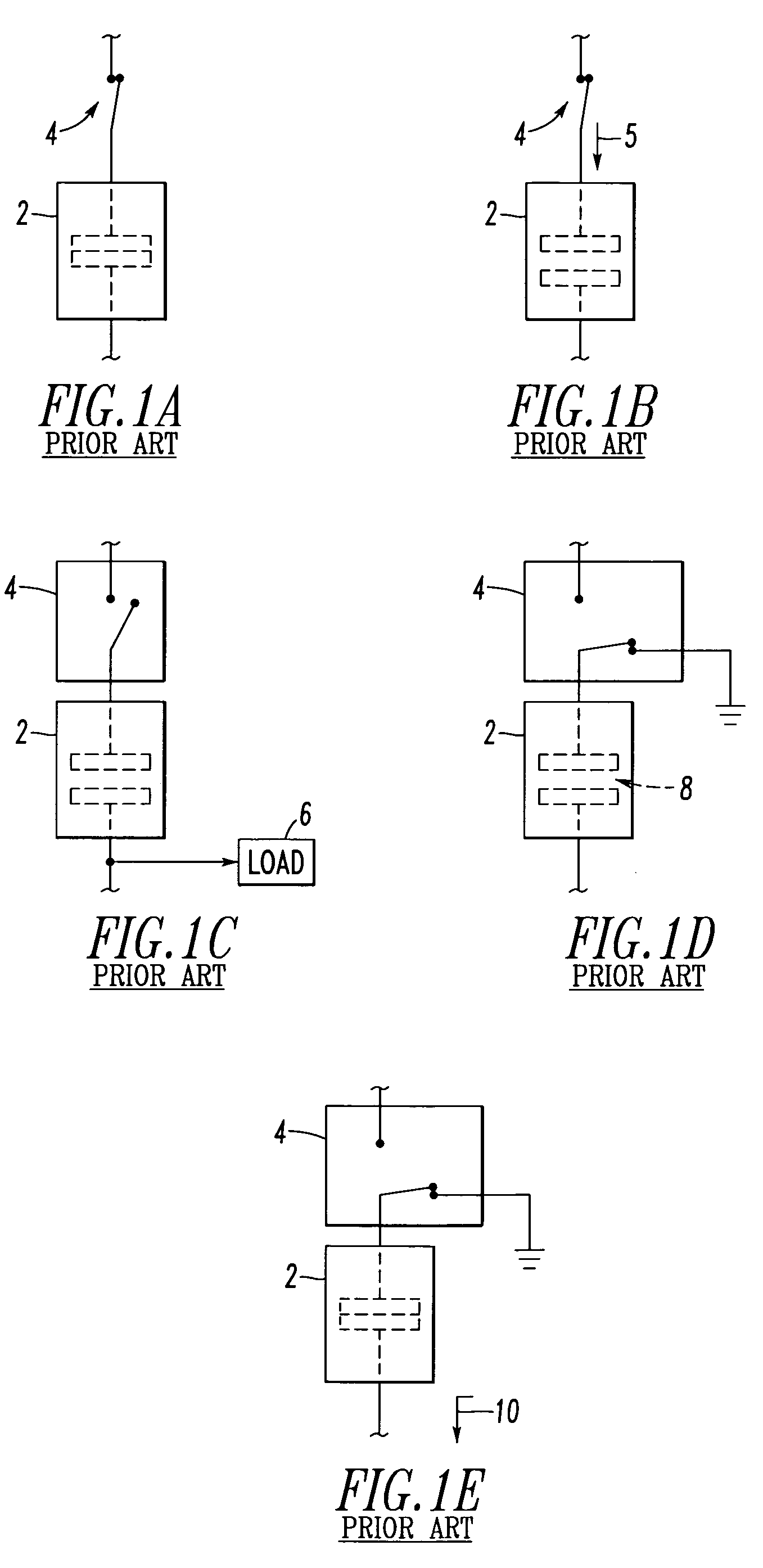
Because of arcing considerations, such a three-position switching and isolating apparatus can generally interrupt or break only very modest levels of current.
These prior proposals all have the inherent disadvantage that the open contact gap in the vacuum envelope has a finite probability of breaking down under a suitably high voltage pulse (e.g., a relatively high voltage pulse resulting from lightning).
In addition, arcing products generated during current interruption could lead to a breakdown between the line and ground contacts, rather than the line and interruption contacts.
If a breakdown were to occur during the disconnect function (i.e., after the off position but before the earth position of a four-position vacuum interrupter), then it would violate the standards requirements for dielectric coordination, and could potentially endanger personnel on the load side of the vacuum interrupter.
In addition, the four-position vacuum interrupters have a significantly more complicated design than current vacuum interrupter designs and would, therefore, be much more difficult to manufacture and be more expensive.

Method used


Image

  • Three-position vacuum interrupter disconnect switch providing current interruption, disconnection and grounding
  • Three-position vacuum interrupter disconnect switch providing current interruption, disconnection and grounding
  • Three-position vacuum interrupter disconnect switch providing current interruption, disconnection and grounding

Examples


example 1

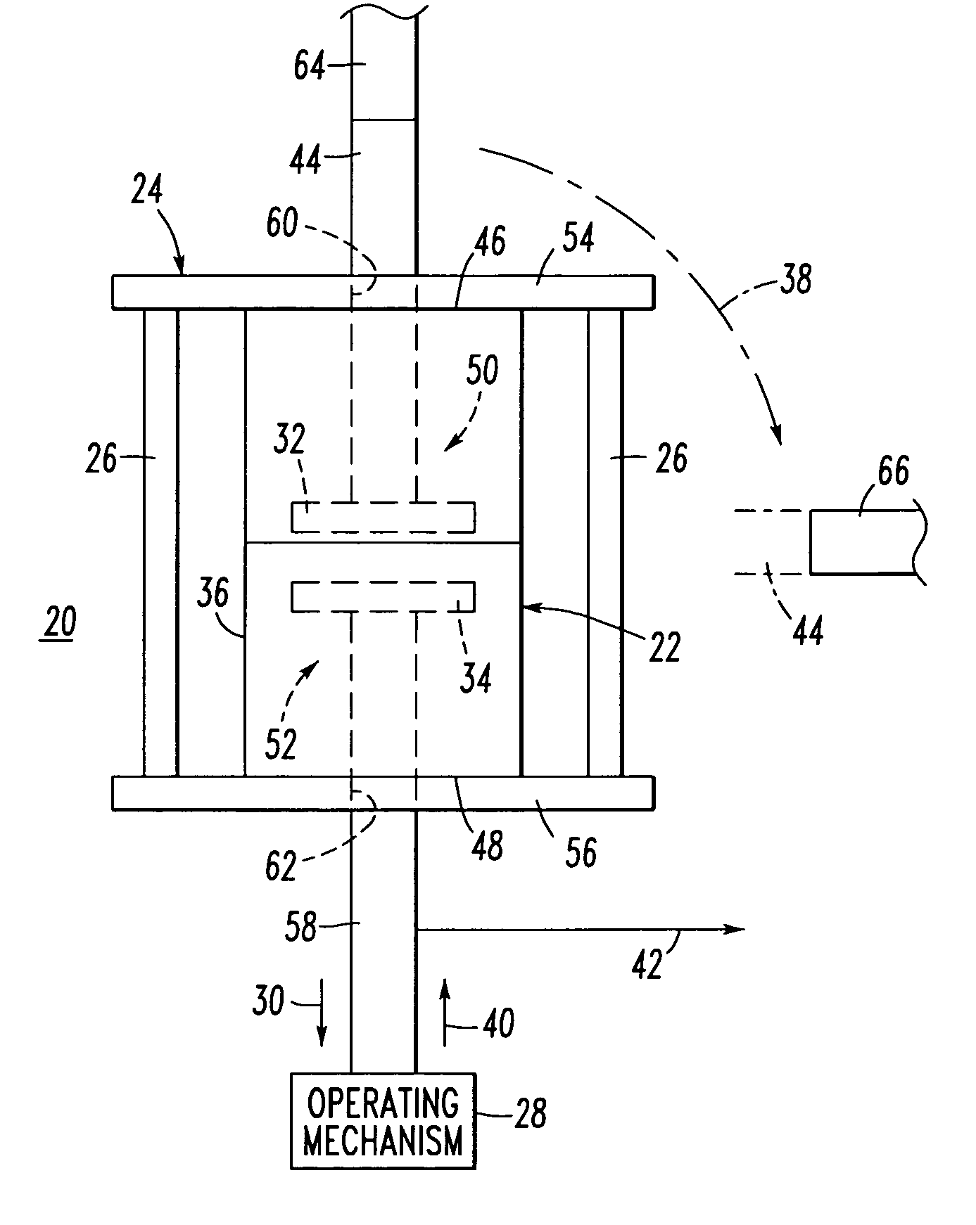
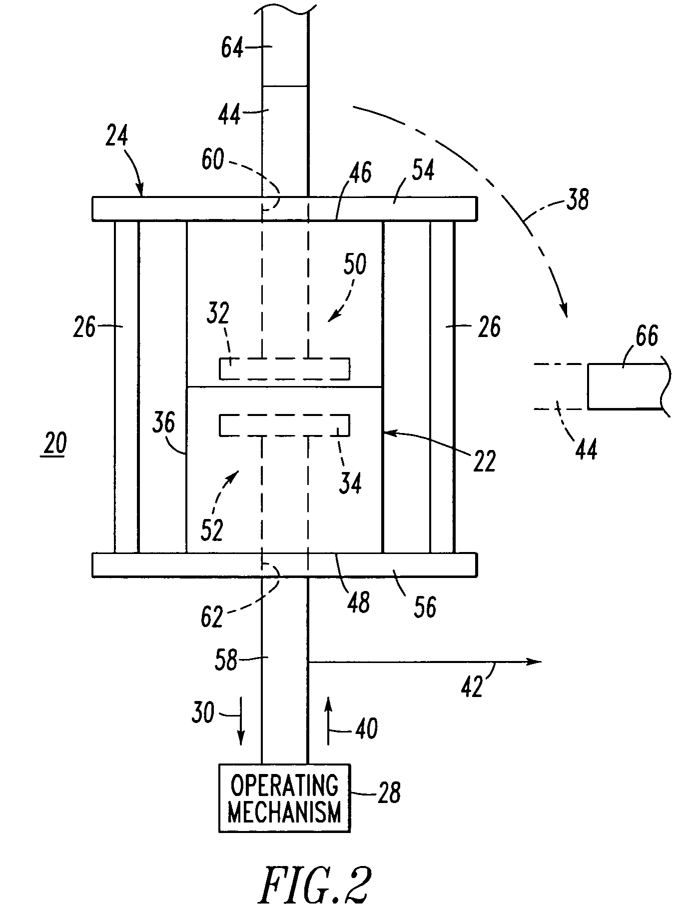
[0037]FIG. 2 shows a vacuum interrupter disconnect switch 20 including a vacuum switch, such as vacuum interrupter 22, enclosed in a suitable insulating cage 24 having a number of insulating members, such as a plurality of insulating support rods 26. Although plural rods 26 are shown, any suitable insulating support member(s) may be employed, such as, for example, that encapsulate the vacuum interrupter 22 in a rigid epoxy resin housing, or such as an insulating support cylinder (not shown). The combined vacuum interrupter 22 and insulating cage 24 is coupled to a suitable operating mechanism 28 in such a way that the operating mechanism provides an initial longitudinal motion (e.g., downward with respect to FIG. 2 as shown by arrow 30) to open the fixed contact 32 (shown in hidden line drawing) and the movable contact 34 (shown in hidden line drawing) inside the vacuum envelope 36, thereby interrupting the circuit current. Then, after this has been achieved, the operating mechanism...

example 2

[0042]FIGS. 3A–3E show the operation of a vacuum interrupter disconnect switch 20′, which is somewhat similar to the switch 20 of FIG. 2. FIG. 3A shows the vacuum interrupter 22, insulating cage 24 and a series switch formed by conductor 44 and a line conductor, such as terminal 68, in a suitable insulating medium, such as air 70, in the closed position.

[0043]In FIG. 3B, the vacuum interrupter 22 is in the open position. The operating mechanism 28 (shown in FIG. 3A) pulls the contacts 32,34 of the vacuum interrupter 22 open and the AC current is interrupted, with the series switch formed by conductor 44 and terminal 68 still being closed. The operating mechanism 28 opens the fixed contact assembly 50 and the movable contact assembly 52 by moving the movable contact assembly 52 along a longitudinal axis defined by the movable stem 58 and away from the fixed contact assembly 50.

[0044]FIG. 3C shows the whole vacuum interrupter 22 and insulating cage 24 being rotated away from its elect...

example 3

[0048]FIGS. 4A–4E show the operation of a vacuum interrupter disconnect switch 20″, which is somewhat similar to the switch 20′ of FIGS. 3A–3E. FIG. 4A shows the vacuum interrupter 22, insulating cage 24 and a series switch formed by conductor 44 and a line conductor, such as terminal 68′, in a suitable insulating medium, such as air 70, in the closed position.

[0049]In FIG. 4B, the vacuum interrupter 22 is in the open position. The operating mechanism 28′ (FIG. 4A) pulls open the contacts 32,34 of the vacuum interrupter 22 and the AC current is interrupted, with the series switch formed by conductor 44 and terminal 68′ still being closed. The operating mechanism 28′ opens the fixed contact assembly 50 and the movable contact assembly 52 by moving the movable contact assembly 52 along the longitudinal axis defined by the movable stem 58 and away from the fixed contact assembly 50.

[0050]Unlike FIG. 3C, FIG. 4C shows the insulating cage 24, vacuum interrupter 22 and conductor 44 being ...


PUM


Abstract

A vacuum circuit interrupter includes a line conductor, a vacuum interrupter, a load conductor, a ground conductor and an operating mechanism. The vacuum interrupter includes a fixed conductor and a vacuum envelope containing a fixed contact and a movable contact movable between a closed circuit position in electrical connection with the fixed contact and an open circuit position spaced apart from the fixed contact. The fixed conductor is outside of the vacuum envelope and is electrically connected to the fixed contact. The load conductor is electrically connected to the movable contact. The operating mechanism is structured to: open and close the fixed and movable contacts, and move the vacuum interrupter and the fixed conductor thereof between a first position wherein the fixed conductor is electrically connected to the line conductor, and a second position wherein the fixed conductor is electrically connected to the ground conductor.

Description

BACKGROUND OF THE INVENTION[0001]1. Field of the Invention[0002]This invention pertains generally to circuit interrupters and, more particularly, to vacuum circuit interrupters, such as, for example, vacuum circuit breakers. The invention also pertains to disconnect switches that provide a grounding function.[0003]2. Background Information[0004]Circuit interrupters provide protection for electrical systems from electrical fault conditions such as, for example, current overloads and short circuits. Typically, circuit interrupters include a spring powered operating mechanism which opens electrical contacts to interrupt the current through the conductors of an electrical system in response to abnormal conditions, although a wide range of mechanical or electromechanical driving mechanisms may be employed.[0005]Vacuum circuit interrupters (e.g., vacuum circuit breakers; vacuum reclosers; other vacuum switching devices) include separable contacts disposed within an insulating housing. Vac...

Claims


Application Information

Patent Timeline
IPC IPC(8): H01H33/66
CPCH01H33/6661H01H33/127H01H31/003H01H33/125
Inventor SLADE, PAUL G.TAYLOR, ERIK D.
Owner EATON INTELLIGENT POWER LIMITED
Learn More