Borescope for drilled shaft inspection

a technology for drilling shafts and inspection equipment, which is applied in the direction of borehole/well accessories, instruments, surveys, etc., can solve the problems of incomplete inspection, incomplete inspection, and final shaft defects that can influence the structural and bearing capacity of the finished support structure, so as to achieve reliable and accurate visual inspection, save the number of inspections, and save the effect of storage and retrieval

Inactive Publication Date: 2007-03-06
AVER TECH INC
View PDF17 Cites 29 Cited by
  • Summary
  • Abstract
  • Description
  • Claims
  • Application Information

AI Technical Summary

Benefits of technology

[0009]Embodiments of the invention overcome one or more deficiencies in the prior art by providing, among other things, an improved system for reliably and accurately visually inspecting relatively large construction boreholes such as those prepared for building drilled shaft foundations. The invention advantageously provides a visual inspection of the adequacy of boreholes (e.g., their bottom and sides) to construct deep foundations or slurry walls. Embodiments of the invention also determine the strength of the materials at the bottom of the boreholes as well as the physical and electrical properties, the pressure, and the temperature of the slurry in the borehole. This is accomplished by a portable system utilizing a miniature charge coupled device (CCD) camera in a watertight assembly and a miniature penetrometer The system of the present invention provides a smaller and lighter device for drilled shaft inspection that a single user can operate. Further, the invention does not require a complicated assembly but can be assembled on-site just prior to use. In one embodiment, an improved inspection system of the invention collects data in analog and / or digital form and is capable of providing digital information to a computer. Thus, it is economical in terms of the number of required personnel and efficient in storing and retrieving the needed information. Advantageously, the present invention is particularly well-suited for inspection in waterways projects and even provides clear vision in environments where visibility is limited. Moreover, the features of the present invention described herein are less laborious and easier to implement than currently available techniques as well as being economically feasible and commercially practical.

Problems solved by technology

However, such assumptions are not always warranted.
Unless project specifications and procedures are closely followed in the field, for example, the final shaft may have defects that can influence its structural and bearing capacity when filled.
Defects of a finished support structure and the conditions under which such defects occur may involve a number of causes.
For example, defects typically result from one or more of the following: 1) over stressing the soil beneath the shaft base due to insufficient bearing (contact) area or because of unconsolidated materials located at the shaft base; 2) excessive mixing from mineral slurry, which can affect the development of concrete strength and / or formation of voids and cavities within the set concrete; and 3) structural discontinuities and / or deviations from the true vertical line causing local, undesirable stress concentrations.
In general, these and other defects can result in insufficient load transfer reducing the bearing capacity of the final structure and / or causing excessive settling during service.
Shaft failures have been attributed to insufficient borehole cleaning, and cleaning the base of boreholes often requires special tools.
As may be expected, verifying the conditions existing at the shaft base is often a difficult task.
Lowering a human inspector into a borehole, especially one that has been stabilized with slurry, can be very dangerous or even impossible.
Since its inception, the SID has been used with only modest success.
The SID weighs approximately 10,000 pounds, is quite large, and is relatively expensive.
Although the idea of utilizing an optical device to inspect drilled shafts has been favored by engineers and contractors, the operation of present devices like the SID is cumbersome, time consuming, expensive, and often produces disappointing results, especially on drilled shaft projects in waterways.
In addition to the high cost of the device itself, the SID's lack of mobility and versatility, particularly in waterways projects, results in higher operating costs.

Method used


Image

  • Borescope for drilled shaft inspection
  • Borescope for drilled shaft inspection
  • Borescope for drilled shaft inspection

Examples


Embodiment Construction

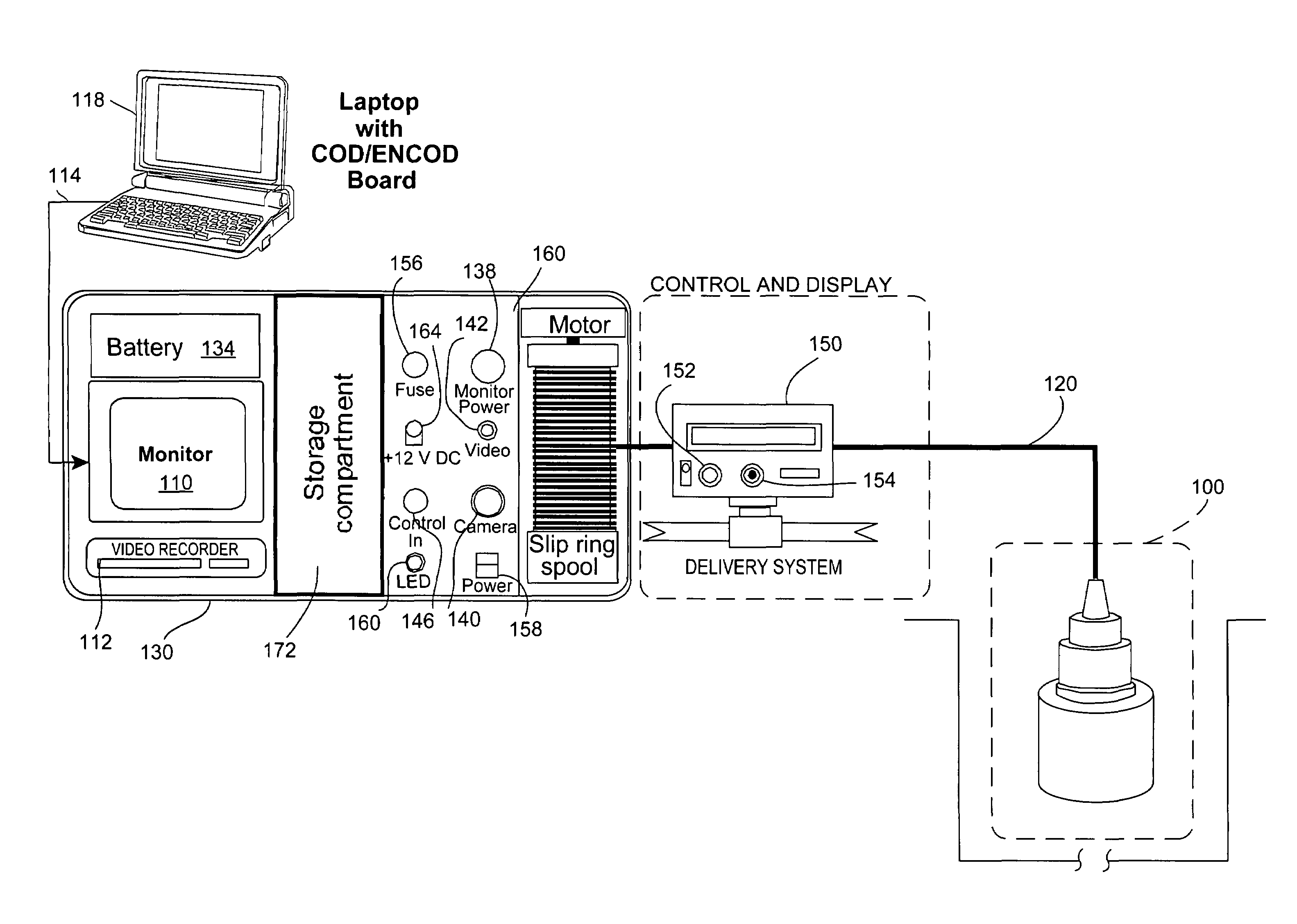
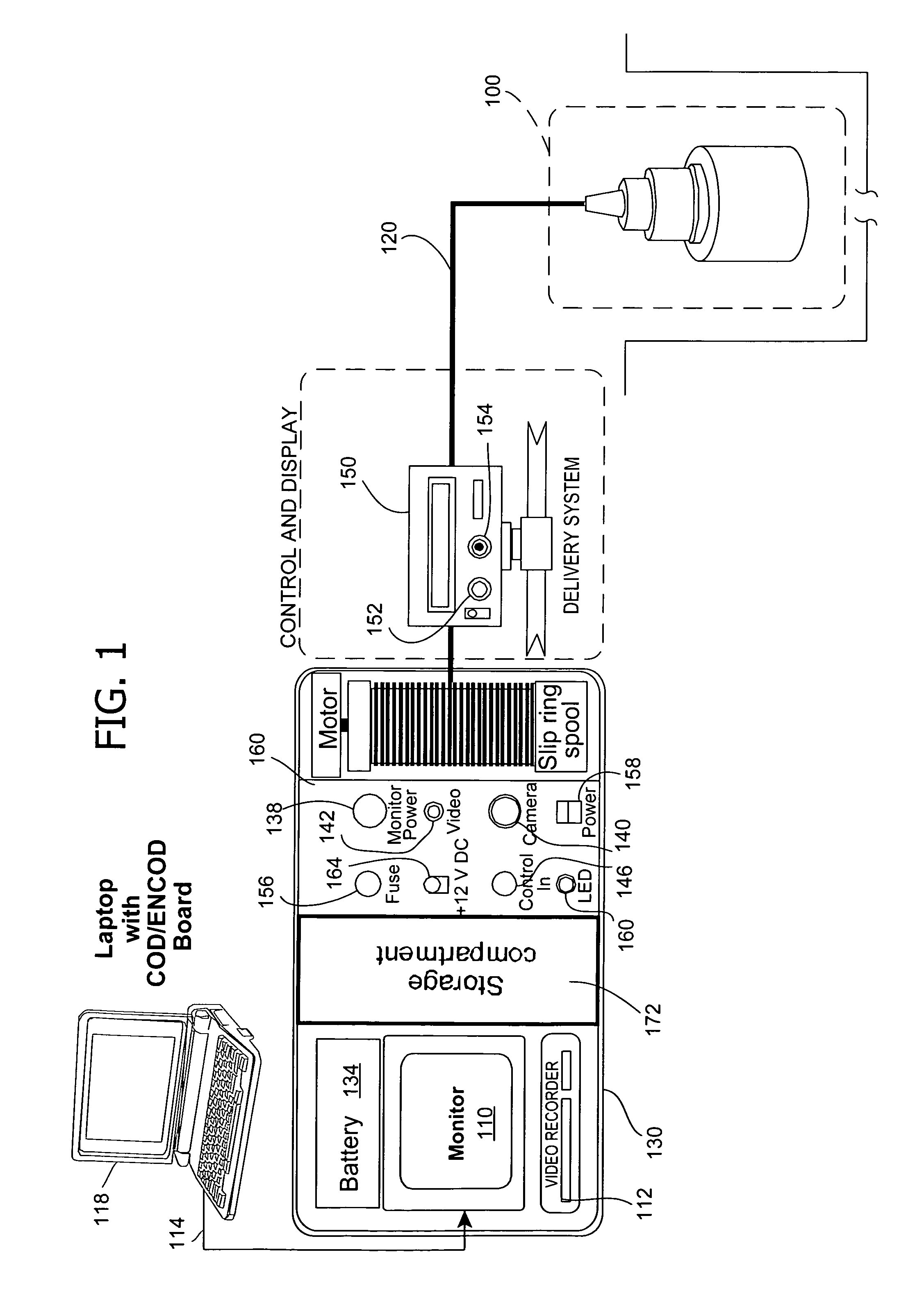
[0028]Referring now to the drawings, FIG. 1 illustrates a borescope system in block diagram form. As shown, the system includes a camera assembly 100 connected to a video monitor 110 (e.g., a relatively small, portable television) for visually inspecting a borehole. A typical borehole is several feet in diameter (e.g., about nine feet) and has an even greater depth (e.g., about 150 feet). It is to be understood, however, that a borehole describes any opening in the ground that has either a generally cylindrical geometry of a few inches to several feet in diameter and depth or a generally rectangular cutoff wall in the ground with a few inches to several feet in width / depth. The borehole can be dry or wet (at least partially filled with transparent, translucent, or opaque fluid). The borehole can be self supported, cased, or a pipe pile. The ratio of the size of the borehole to the camera chamber can be 1:1 or 28:1.

[0029]As described in detail below, the present system may be used to...


PUM

PropertyMeasurementUnit
depthaaaaaaaaaa
depthaaaaaaaaaa
diameteraaaaaaaaaa

Abstract

Visual inspection of an interior surface of a borehole. A housing adapted to be lowered in the borehole supports a portable camera for generating images of a portion of the interior surface of the borehole and a light source for illuminating an area adjacent the camera. A monitor receives signals from the camera and, in response thereto, displays the images generated by the camera. A viewing envelope positioned adjacent the camera defines a viewing area adjacent the camera, particularly for use in visually inspecting slurry-filled boreholes.

Description

CROSS REFERENCE TO RELATED APPLICATION[0001]This application is a continuation-in-part of application Ser. No. 09 / 409,450, filed Sep. 30, 1999 now abandoned, which claims the benefit of provisional application Ser. No. 60 / 102,408, filed Sep. 30, 1998, the entire disclosures of which are incorporated herein by reference.BACKGROUND OF THE INVENTION[0002]The invention relates generally to a borescope system for use in inspecting drilled shafts, also referred to as bores or boreholes. In particular, the invention relates to a portable visual inspection system for inspecting relatively large drilled construction shafts and the like that provides improved efficiency in terms of maneuverability, information gathering, data recording, data analyzing, and data quantifying.[0003]Drilled construction shafts that are subsequently filled with concrete or similar materials provide support for many large building projects. For this reason, field engineers and inspectors involved in preparing such ...

Claims


Application Information

Patent Timeline
Patent Type & Authority Patents(United States)
IPC IPC(8): G06K9/00A61B1/04E21B47/00G01V1/40G01V3/18G01N21/954H04N7/18
CPCE21B47/0002G01N21/954E21B47/002
Inventor TAWFIQ, KAMALMALLORY, EDWARD J.PUTCHA, SASTRYTURNER, DAN
Owner AVER TECH INC
Why Eureka
Try Eureka