
Coil sensitivity map generating method, parallel imaging method, and MRI apparatus

a sensitivity map and generating method technology, applied in the field of parallel imaging method, mri (magnetic resonance imaging) apparatus, can solve the problems of large inhomogeneity of image obtained by conventional self-calibration, inability to achieve optimal image homogeneity,

Inactive Publication Date: 2007-03-06
GE MEDICAL SYST GLOBAL TECH CO LLC
View PDF6 Cites 7 Cited by
  • Summary
  • Abstract
  • Description
  • Claims
  • Application Information

AI Technical Summary

Benefits of technology

[0016]It is therefore an object of the present invention to provide a coil sensitivity map generating method, parallel imaging method, and MRI apparatus that can improve homogeneity of an image obtained in a self-calibration.

Problems solved by technology

However, while the sensitivity factors Sn(p)′ calculated using the additive square root image As=sqrt{ΣCn2} of the square images Cn2 of the complex images Cn offer an excellent S / N ratio, they are not optimal in view of image homogeneity.
That is, the image obtained by the conventional self-calibration suffers from a disadvantage of large inhomogeneity.

Method used


Image

  • Coil sensitivity map generating method, parallel imaging method, and MRI apparatus
  • Coil sensitivity map generating method, parallel imaging method, and MRI apparatus
  • Coil sensitivity map generating method, parallel imaging method, and MRI apparatus

Examples


Embodiment Construction

[0068]The present invention will now be described in more detail with reference to embodiments shown in the accompanying drawings.

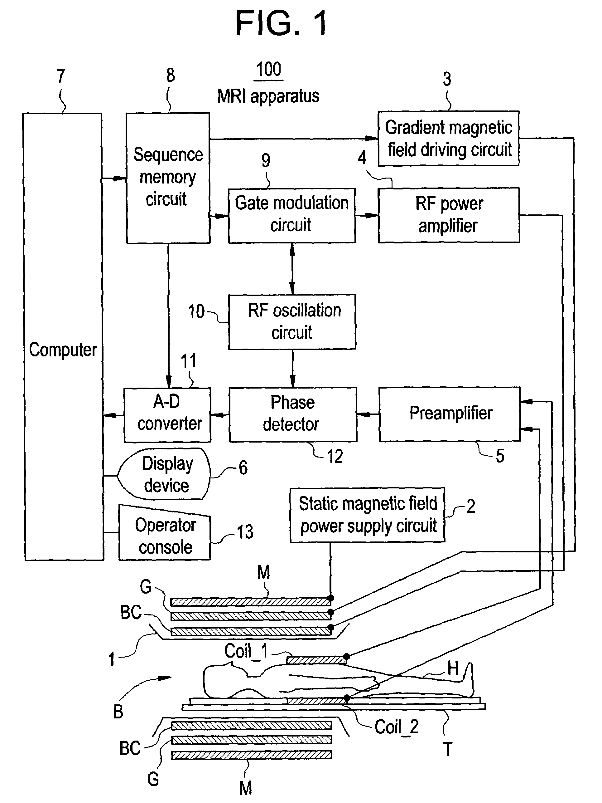
[0069]FIG. 1 is a block diagram showing an MRI apparatus in accordance with one embodiment of the present invention.

[0070]In the MRI apparatus 100, a magnet assembly 1 has a bore B for inserting therein a subject H rested on a table T, and comprises, surrounding the bore B, a static magnetic field coil M for generating a constant static magnetic field, a gradient magnetic field coil G for generating gradient magnetic fields along X-, Y- and Z-axes, and a body coil BC for transmitting an RF pulse.

[0071]Over the trunk of the subject H, phased array coils Coil_1 and Coil_2 are disposed for receiving an MR signal.

[0072]The static magnetic field coil M is connected to a static magnetic field power supply circuit 2; the gradient magnetic field coil G is connected to a gradient magnetic field driving circuit 3; the body coil BC is connected to an RF power amplif...


PUM


Abstract

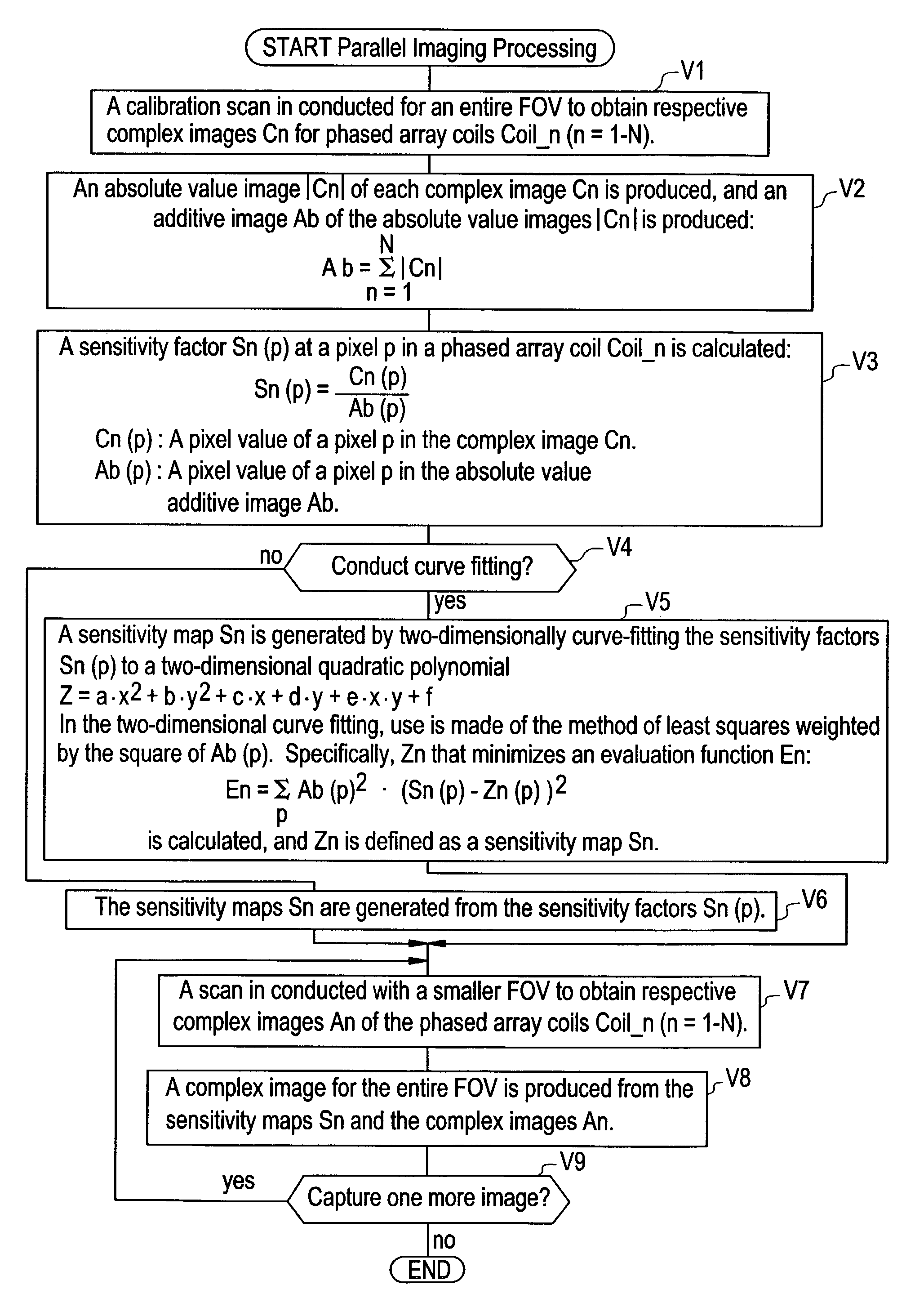
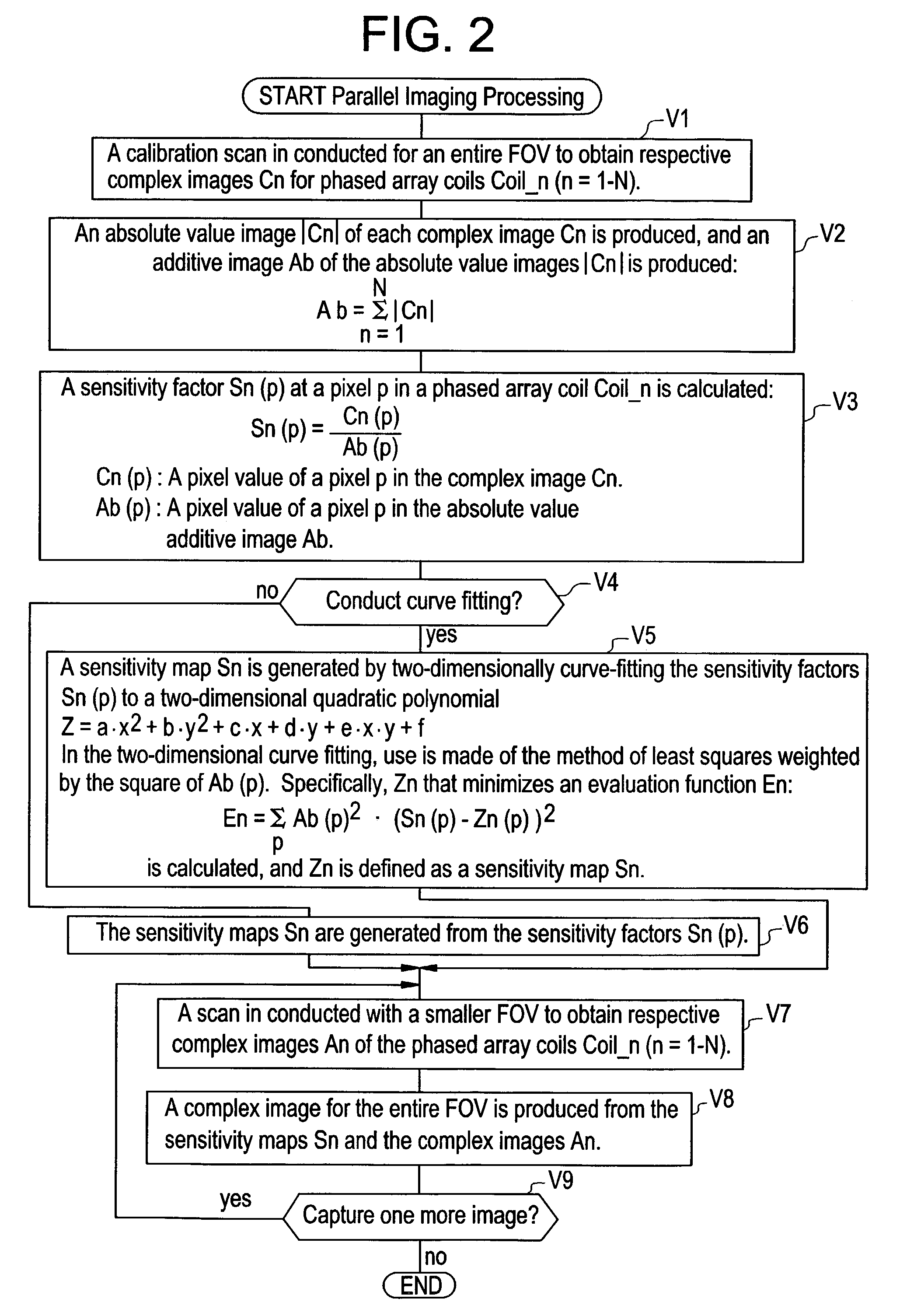
For a purpose of improving homogeneity of an image obtained in a self-calibration by a parallel imaging method generally referred to as SENSE (SENSitivity Encoding), sensitivity factors Sn(p) are calculated using an additive image Ab=Σ|Cn| of complex images Cn obtained by conducting a calibration scan of an entire FOV for phased array coils Coil_n (n=1–N, N≧2) (Steps V2, V3). Moreover, sensitivity maps Sn are generated by conducting curve fitting by the method of least squares weighted by the square of a pixel value Ab(p) of the absolute value additive image Ab (Step V4).

Description

CROSS REFERENCE TO RELATED APPLICATIONS[0001]This application claims the benefit of Japanese Application No. 2002-166994 filed Jun. 7, 2002.BACKGROUND OF THE INVENTION[0002]The present invention relates to a coil sensitivity map generating method, parallel imaging method, and MRI (magnetic resonance imaging) apparatus, and more particularly to a coil sensitivity map generating method, parallel imaging method, and MRI apparatus that can improve homogeneity of an image obtained in a self-calibration by a parallel imaging method generally referred to as SENSE (SENSitivity Encoding).[0003]Conventional techniques relating to SENSE are described in, for example, the following literature:[0004](1) Pruessmann, K. P., Weiger, M., Scheidegger, M. B., and Boesiger P., Magn. Reson. Med., 42, 952 (1999); and[0005](2) P. B. Roemer, W. A. Edelstein, C. E. Hayes, S. P. Souza, and O. M. Mueller, Magn. Reson. Med., 16, 192–225 (1990).[0006]FIG. 5 is a flow chart showing an operation of parallel imagi...

Claims


Application Information

Patent Timeline
IPC IPC(8): G06K9/00G01R33/54A61B5/055G01R33/36G01R33/561
CPCG01R33/5611A61B5/055
Inventor IKEZAKI, YOSHIKAZU
Owner GE MEDICAL SYST GLOBAL TECH CO LLC
Learn More